English
Turn on the LED
The lighting program is the first program to learn all the development boards, just like learning all programming languages, it has a sacred meaning.
Circuit
As we all know, lighting an LED requires a power supply, a resistor, and an LED bulb,
There are three LEDs on the Maix Dock development board, the wiring is as follows:
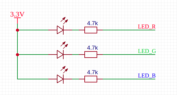
For example, we want the red light to light up, that is, the LED connected to LED_R. As you can see in the picture, the anode of the LED has been connected to a 3.3V power supply, so we only need to make LED_R a low-level LED to light up.
Note that here
LED_Ris an alias for this pin, which is actually connected to a pin of the chip, such asPin13orIO13
FPIOA (Field Programmable Input and Output Array)
Maybe you have used some single-chip microcomputers, and the manual stipulates the binding of pins and on-chip peripheral functions (that is, the peripherals integrated in the chip, such as GPIO, I2C, SPI, etc.), or re Mapping. For example, it is stipulated that I2C can only use Pin9 and Pin10. After the remapping function is enabled, only Pin11 and Pin12 can be used
However, the pins (hardware pins) corresponding to the on-chip peripherals of the hardware K210 used by MaixPy can be arbitrarily mapped. In contrast, the K210 hardware design and software design have more freedom. For example, I2C can use Pin11 and Pin12, and can also be changed to any other pin
Pay attention to distinguish the difference between
GPIOandIO.IOcan also be calledPin, which is a hardware pin derived from the chip, andGPIOis a peripheral device that can control these Peripherals ofPin/IO
Because of this powerful mapping function, when using pins, you need to add a step of mapping:
from fpioa_manager import fm # import library
fm.register(28, fm.fpioa.GPIO0)
Here we map pin 28 to the function of GPIO0. After executing this command, pins 28 and GPIO0 are mapped (bound). If you want to unmap (unbind), then Need to call the fm.unregister function, see the API documentation for details, not introduced here
In addition, Pin and peripherals can only correspond unique, not one-to-many. It is necessary to map the same peripherals or pins repeatedly, otherwise the program may produce errors that are difficult to find (BUG)
Code
We need to use GPIO to control the LED
The procedure is as follows:
from fpioa_manager import fm
from Maix import GPIO

io_led_red = 13
fm.register(io_led_red, fm.fpioa.GPIO0)

led_r=GPIO(GPIO.GPIO0, GPIO.OUT)
led_r.value(0)
Run the code in the terminal according to the previous method of running the code, and you will find that the LED light is lit!
Next we analyze the code:
Import the
fmobject from thefpioa_managerpackage, which is mainly used for pin and peripheral mappingImported the class
GPIOfrom packageMaix, GPIO peripheral related operationsDefine a variable
io_led_red, the value is13, that is,Pin13/IO13, which pin of the chip is connected to the specific LED pin, please see the schematic in the previous development board introductionUse the built-in object
fm(abbreviation of fpioa manager) to register the correspondence between the peripherals of the chip and the pins, herefm.fpioa.GPIO0is a GPIO peripheral of K210 (pay attention to distinguish GPIO (external Set) and the difference between pins (real hardware pins)), sofm.fpioa.GPIO0is registered to pinIO13;Then define a
GPIOobjectled_r, see theGPIOAPI documentation for specific parameters, and find it in the left sidebar.Use
led_r.value(1)orled_r.value(0)to set the high and low levels, because the low level is set here. According to the above schematic diagram, it can be seen that the low level is on and the LED is on
Now you can light up the lights. Now you can try to use the for loop to achieve the LED flashing or running lights~ to make different transformation effects