English
MaixCAM MaixPy Pinmap Usage Introduction
Update history
| Date | Version | Author | Update content |
|---|---|---|---|
| 2025-08-08 | 1.1.0 | Neucrack | Refactored the document for better understanding by beginners |
| 2024-06-11 | 1.0.0 | iawak9lkm | Initial version of the document |
What is a Pin
A pin is a physical hardware pin exposed from the chip/development board. They are visible and tangible around the chip package. In English, we refer to them as Pin.
What is an On-chip Peripheral
These are components built into the chip, other than the CPU cores. The “external” here is relative to the CPU core (internal), as opposed to “off-chip modules” which are external to the entire chip.
For example, the following is the internal architecture diagram of the MaixCAM/MaixCAM-Pro chip:
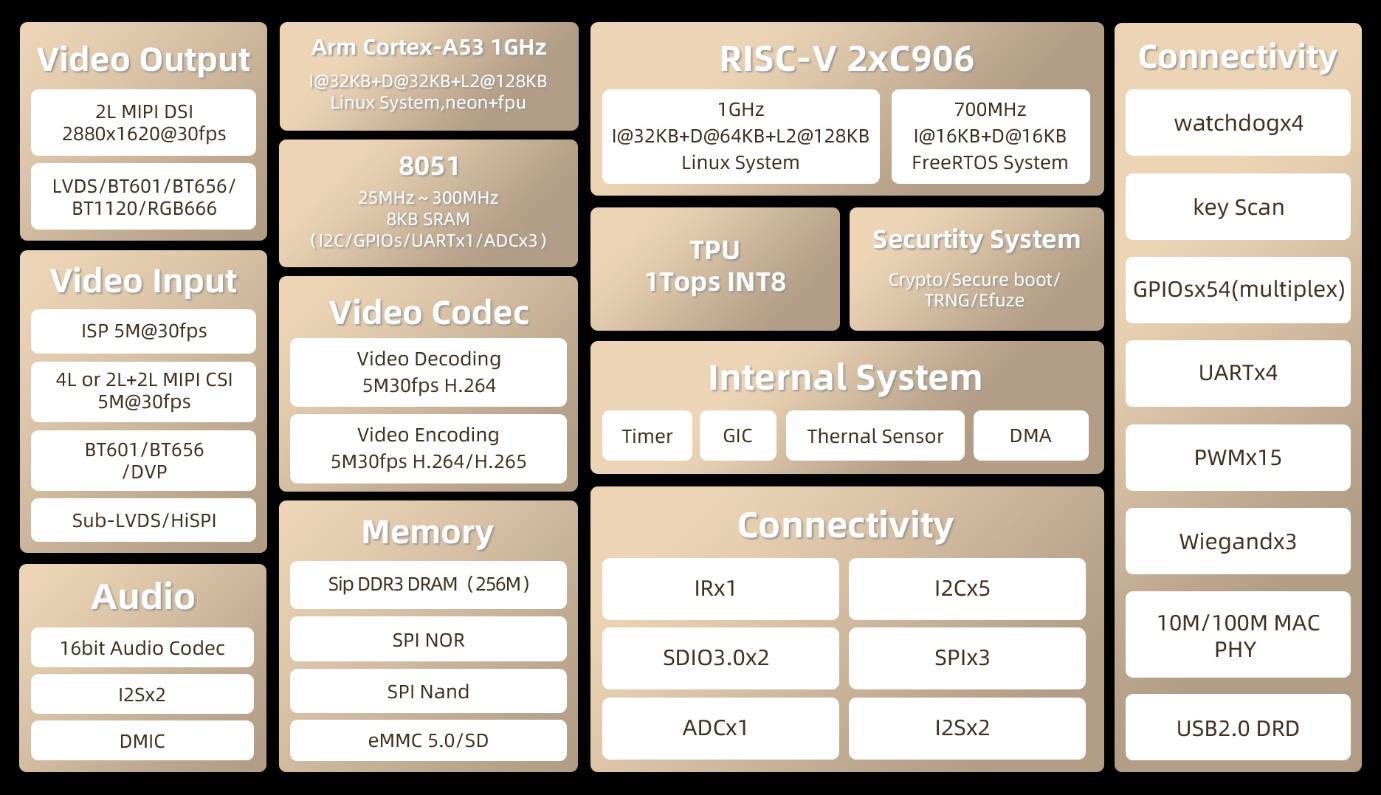
We can see that the core consists of two RISC-V cores and one 8051 core. In addition, there are many peripherals such as GPIO, UART, and H.264 codec, all of which are considered on-chip peripherals.
Importantly, peripherals here do not necessarily require pins to be brought out of the chip — for example, the H.264 codec is also a peripheral but does not need external pins for interaction.
Also note that here GPIO is a peripheral function within the chip and is not the same as the physical pins (Pin) exposed from the chip.
What is Pin Multiplexing / Pin Mapping
For peripherals that require interaction with the outside world, such as GPIO or I2C,
GPIOcan control pin input/output,I2Ccan communicate with other chips via two pins (SDA/SCL).
The simplest design is one pin for each function: for example, in the architecture diagram above, GPIO has 54 pins, and I2C has 5 sets, requiring a total of 54 + 2 × 5 = 64 pins.
The more functions that require pins, the more pins need to be exposed from the chip, which increases chip size. In reality, it’s rare to need all 54 GPIOs and all 5 I2Cs simultaneously.
We can add a pin multiplexing circuit between peripherals and pins, so a single pin can switch between GPIO and I2C. This way, fewer pins can support more functions.
For example, with 50 pins, 10 of them could be configured either as GPIO or as I2C. This is pin multiplexing, usually called pinmux in English.
Due to hardware design limits, most chips allow a pin to be mapped to only a few fixed functions. For example, the MaixCAM-Pro pin mapping is shown below:
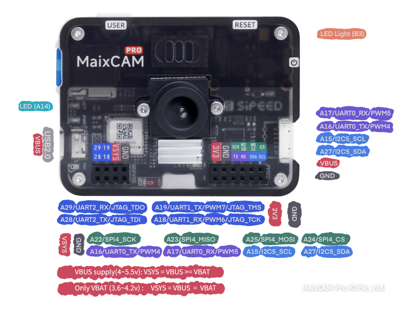
Take the A17 pin on the right: it supports three functions — GPIOA17 / UART0_RX / PWM5. We can select which function to use.
If the default is UART0_RX but we need PWM5, we configure the pinmux accordingly.
In MaixPy, the maix.peripheral.pinmap module (or simply maix.pinmap) is used to query and set pin multiplexing (pin function mapping).
Other benefits of pin multiplexing:
- Save pin count: SoCs integrate many modules (CPU, GPU, memory controllers, I/O interfaces, communication modules, etc.). Assigning separate pins to each function would require huge pin counts, increasing packaging complexity and cost. Pinmux allows one pin to serve multiple purposes, reducing pin numbers significantly.
- Reduce packaging & manufacturing cost: Fewer pins allow for smaller chip packages, lowering material and manufacturing costs. Smaller packages also save PCB space, enabling more compact designs.
- Increase design flexibility: Pinmux provides flexibility for different application scenarios by enabling different pin functions via software configuration.
- Simplify PCB layout: Fewer pins make PCB routing easier, reducing layers and vias, which lowers production difficulty and cost.
- Optimize performance: Choosing optimal pin functions can shorten signal paths and reduce noise/interference, improving overall system reliability.
Using Pinmap in MaixPy
Pin Function Diagrams
Different boards expose different pins. Below are pin mapping diagrams for each device. For detailed mappings, refer to the schematic or the chip manual’s Pinmux section:
| Device Model | Pin Diagram | Description | Full Schematic & Datasheet |
|---|---|---|---|
| MaixCAM | 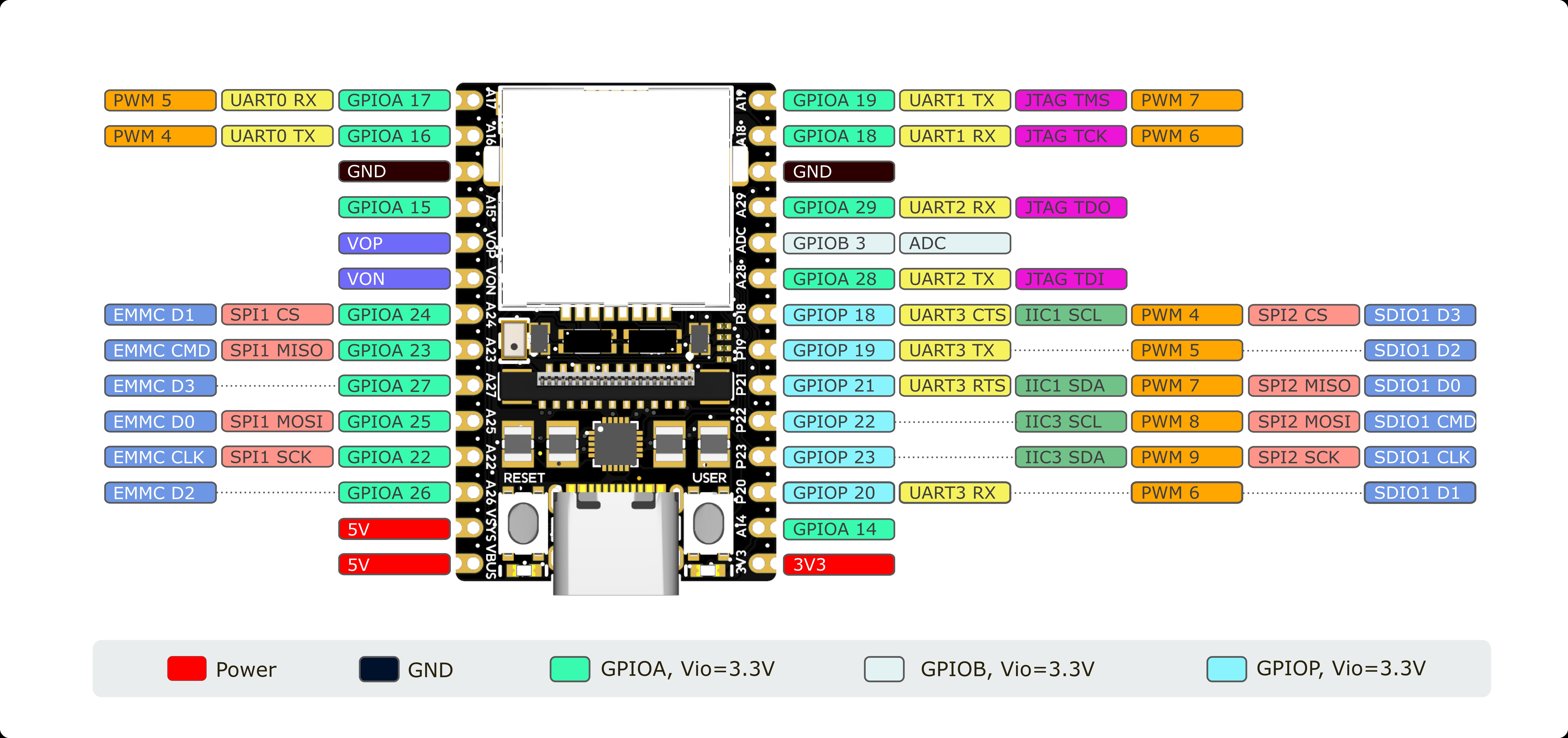 |
Silkscreen like A19 is the pin name; GPIOA19/PWM7 is the function name |
See Hardware Docs |
| MaixCAM-Pro | |
First name like A19 is the pin name; GPIOA19/PWM7 is the function name |
See Hardware Docs |
| MaixCAM2 | 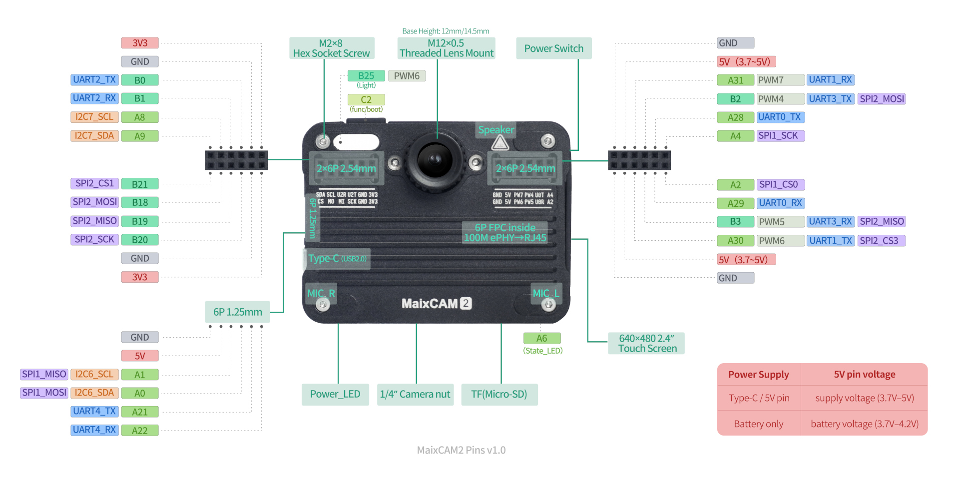 |
First name like A2 is the pin name; GPIOA2/SPI1_CS0 is the function name |
See Hardware Docs |
Note: For MaixCAM2, in the schematics and chip documentation, you may encounter notations like
GPIO1_A25. To make things look cleaner, we define it asB25, which is equivalent. For example,GPIO0_A2corresponds toGPIOA2in MaixPy, andGPIO3_A2corresponds toC2in MaixPy.
Specifically, the n in GPIOn maps as follows: n = 0 corresponds to A in MaixPy, n = 1 corresponds to B. The A25 part of GPIO1_A25 corresponds to 25 in MaixPy, with the A dropped.
Mapping Pin Functions in MaixPy
In MaixPy, use maix.pinmap.set_pin_function to set a pin function.
Example — set A17 pin on MaixCAM/MaixCAM-Pro:
from maix import pinmap

pinmap.set_pin_function("A17", "GPIOA17")
Here A17 is the pin name, and GPIOA17 is the on-chip peripheral function.
This changes the default UART0_RX to GPIO. Now, even if data is sent to UART0, the chip won’t receive it because the pin is in GPIO mode.
After setting to GPIO, follow the GPIO usage docs to output high/low levels or read input.
Get All Functions of a Pin
from maix import pinmap

funcs = pinmap.get_pin_functions("A17")
print(funcs)
Print all pins and their functions:
from maix.peripheral import pinmap

print("All pins of MaixCAM:")
print(pinmap.get_pins())

print("All pin's functions:")
for pin in pinmap.get_pins():
    funcs = pinmap.get_pin_functions(pin)
    print(f"{pin:10s}: {', '.join(funcs)}")
Query Current Function of a Pin
Note: support varies by board type:
- MaixCAM / MaixCAM-Pro: Mapping info is stored in an array, not read directly from hardware, so you must set it first for accuracy (source code here).
- MaixCAM2: Reads directly from hardware, so results are accurate.
from maix import pinmap

func = pinmap.get_pin_function("A17")
print(func)
More Examples
See more in MaixPy Examples.
API Documentation
See the detailed Pinmap API Docs.
Default Pin Functions & Notes
| Device Model | Pin Diagram | Default Function | Pins to Note |
|---|---|---|---|
| MaixCAM | |
Refer to MaixCAM-Pro |
1. UART0 is system log + default serial portWiFi (SDIO1 + A26) 2. A14 is system status LED; after setting to GPIO, it can be used as normal output3. User button already has a system key driver; not recommended to read via GPIO4. IO is 3.3V — do not connect 5V directly |
| MaixCAM-Pro | |
1. Refer to silkscreen, e.g. 29 = GPIO, RX = UART2. 6pin defaults to UART and I2C |
1. Same as MaixCAM2. B3 drives a lighting LED, active high |
| MaixCAM2 | |
1. Refer to silkscreen, e.g. A4 = GPIO, U2R = UART2. 6pin defaults to UART and I2C |
1. B25 drives a lighting LED, active high2. A6 drives system status LED; can be used as GPIO output after init3. IO is 3.3V — do not connect 5V directly |