English
UART
Update history
| Date | Version | Author | Update content |
|---|---|---|---|
| 2025-08-08 | 1.2.0 | Neucrack | Added MaixCAM2 support |
| 2024-08-01 | 1.1.0 | Neucrack | Optimized documentation with more details |
| 2024-03-07 | 1.0.0 | Neucrack | Initial version |
Prerequisite Knowledge
Please first learn to use the pinmap module to set pin functions.
To use a pin for UART functionality, you must first set its function to UART using pinmap.
Serial Port Overview
A serial port is a communication method that includes both hardware and communication protocol definitions.
Hardware includes:
- 3 pins:
GND,RX, andTX. Communication between two devices is cross-connected forRXandTX, meaning one device’sTXconnects to the other’sRX, and bothGNDpins are connected together. - A controller, usually inside the chip, also called a
UARTperipheral. A chip usually has one or moreUARTcontrollers, each with corresponding pins.
- 3 pins:
Serial communication protocol: To ensure proper communication, a protocol defines timing, baud rate, parity bits, etc. The baud rate is the most commonly used parameter.
Through the board’s serial port, you can communicate with other microcontrollers or SoCs. For example, MaixCAM can perform human detection and send the detected coordinates to an STM32/Arduino via the serial port.
Choosing the Appropriate UART to Use
First, we need to know which pins and I2C interfaces are available on the device, as shown below:
| Device Model | Pin Diagram | Pin Multiplexing Description |
|---|---|---|
| MaixCAM | 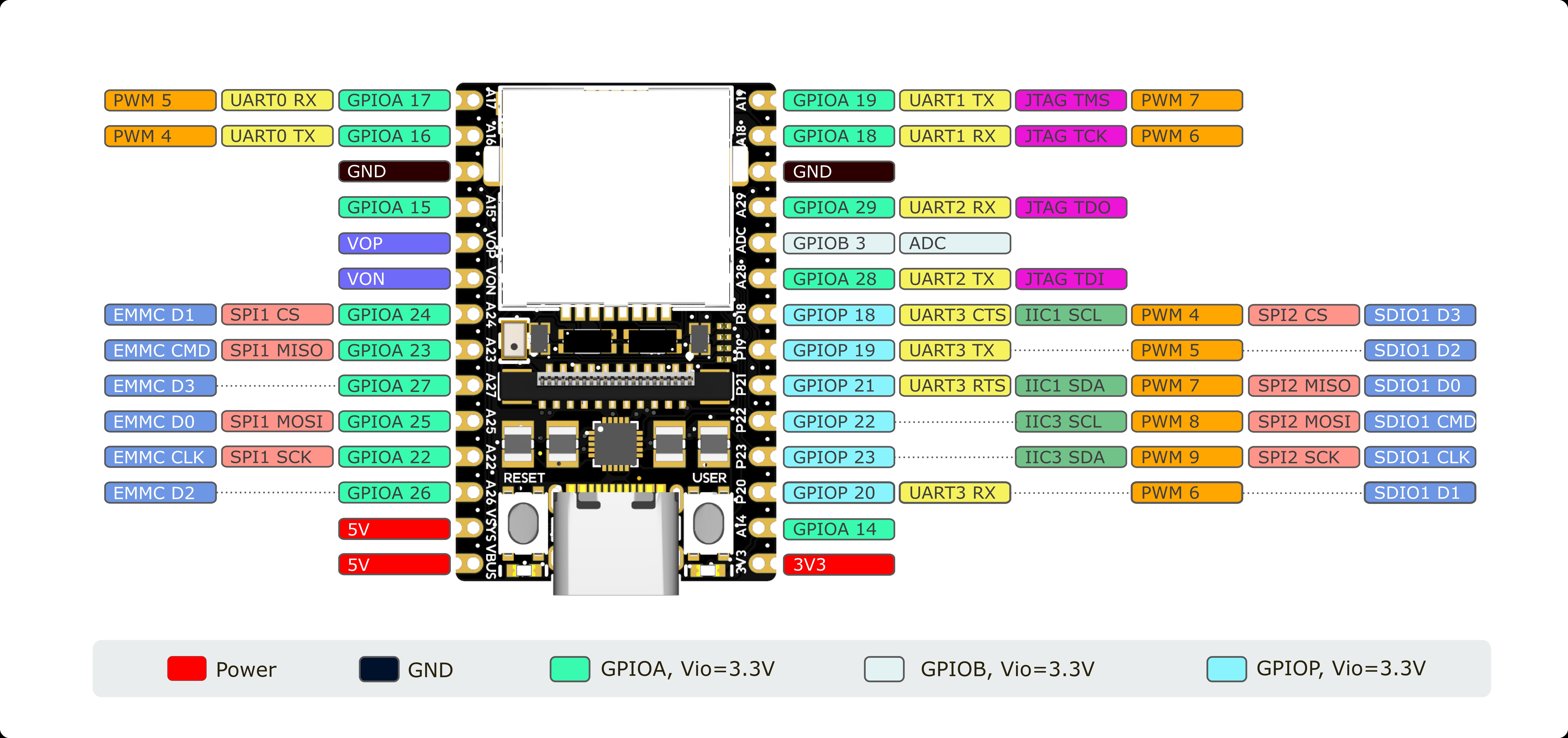 |
The board’s silkscreen shows the pin name (e.g., A19) and function name (e.g., UART1_TX). |
| MaixCAM-Pro | 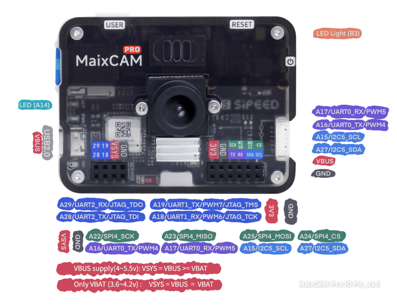 |
The first label (e.g., A19) is the pin name, corresponding to the function name (e.g., UART1_TX). |
| MaixCAM2 | 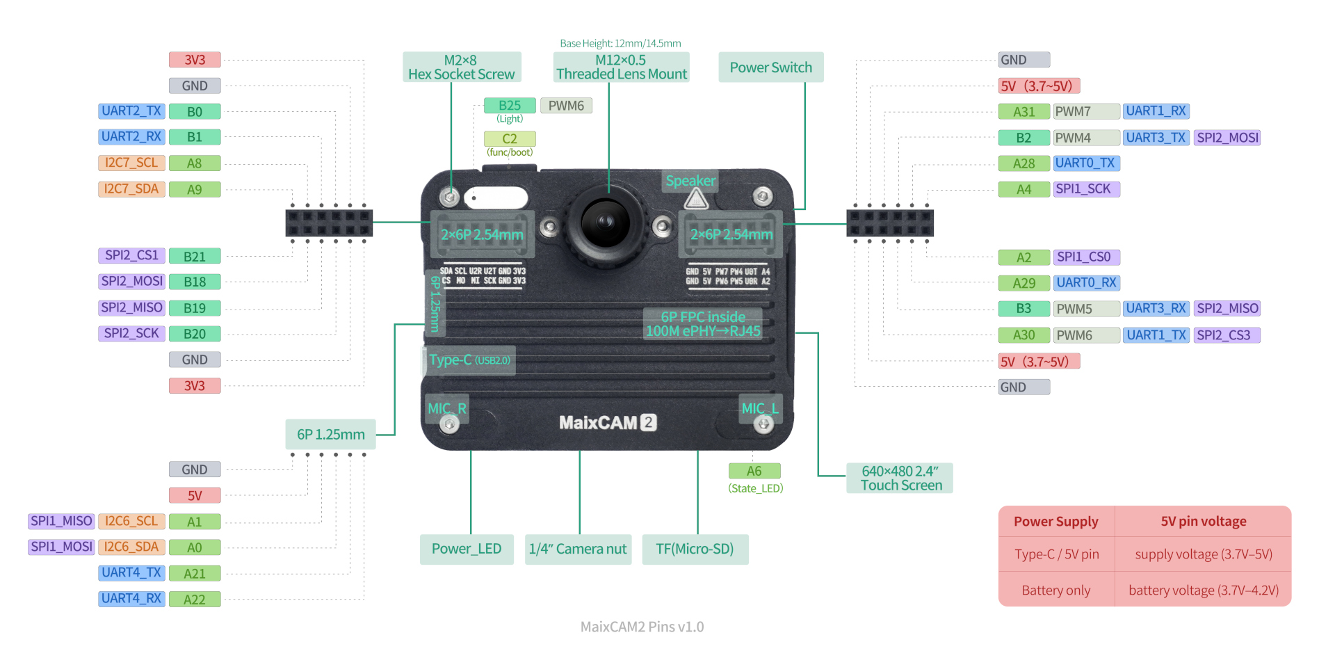 |
The first label (e.g., A21) is the pin name, corresponding to the function name (e.g., UART4_TX). |
Note: Pins may be used for other purposes by default. It’s best to avoid these pins—see the pinmap documentation.
Notes for MaixCAM/MaixCAM-Pro Serial Port Usage:
- By default, a
UART0serial port is routed from the USB port. You can use the matching Type-C adapter board to directly access the serial pins, or you can use the onboardA16 (TX)andA17 (RX)pins, which are equivalent to the USB-exposed serial pins. - When using the USB-exposed serial port on MaixCAM, note that the Type-C plug’s orientation affects the adapter board’s
RXandTXpins (swapped if reversed; silkscreen matches when the Type-C female port faces forward). If communication fails, try flipping the Type-C connector. UART0on MaixCAM prints boot logs during startup and printsserial readywhen boot completes. If communicating with a microcontroller, ignore this initial output. Boot logs can also help diagnose startup issues.- The
TXpin ofUART0is also a boot mode detection pin. It must not be pulled low during power-on, or the device won’t boot. If using a 3.3 V to 5 V level shifter, ensure it doesn’t pullTXlow by default (use a level-shifting chip or keep it floating). If the board won’t start, check ifTXis being pulled low. - If
UART0causes issues, consider using another UART such asUART1. UART0is also the system’s defaultmaix protocolport.
Notes for MaixCAM2:
MaixCAM2has multiple serial ports:UART0 / UART1 / UART2 / UART3 / UART4—don’t mix them up.UART0is the system terminal and log port.
Baud Rate Limitations
Not all baud rates are supported. Unless necessary, use 115200 (universally supported). Other baud rates may have high error rates or be unsupported.
Common tested baud rates (contributions welcome):
MaixCAM / MaixCAM-Pro:115200.MaixCAM2:115200. Theoretical max:4000000 bits/s. Formula:
baud = uart_clk / (fractional_div * 16)
Defaultuart_clk:200000000. Integer part:uart_clk / (baud * 16). Fractional part:round((uart_clk % (baud * 16)) * 16 / (baud * 16)) / 16.
Example: For115200, divisor =108.5, precision =0.0064%.
Serial Port Hardware Wiring
For two devices to communicate, connect three pins: GND, RX, TX. Connect TX of one to RX of the other, and connect both GNDs together.
Using Serial Port in MaixPy
Once the two boards are connected (crossed RX/TX, common GND), you can use the software.
Basic MaixPy code:
from maix import uart

serial_dev = uart.UART("/dev/ttyS0", 115200)
serial_dev.write_str("Hello MaixPy")
/dev/ttyS0 is the serial device. Use print(uart.list_devices()) to list all devices.
For pins that are already mapped to UART, you can use them directly. For others, set their function via pinmap before creating the UART object:
from maix import uart, pinmap, time, sys, err

# ports = uart.list_devices() # list all UARTs

device_id = sys.device_id()
if device_id == "maixcam2":
    pin_function = {
        "A21": "UART4_TX",
        "A22": "UART4_RX"
    }
    device = "/dev/ttyS4"
else:
    pin_function = {
        "A16": "UART0_TX",
        "A17": "UART0_RX"
    }
    device = "/dev/ttyS0"

for pin, func in pin_function.items():
    err.check_raise(pinmap.set_pin_function(pin, func), f"Failed set pin{pin} function to {func}")

serial_dev = uart.UART(device, 115200)
serial_dev.write_str("Hello MaixPy")
Connecting Serial Port to a Computer
Why doesn’t a serial device appear on my computer when I plug in USB?
The board’s USB port is for USB functions (e.g., USB network adapter), not USB-to-UART. For terminal access, use SSH.How to communicate between the computer and board via UART?
Use a USB-to-UART adapter (e.g., this one). Connect USB to the PC and UART to the board.How to view boot logs or interact with the board via UART terminal?
SSH is recommended for terminal interaction. For serial terminal access:- MaixCAM/MaixCAM-Pro: Connect USB-to-UART adapter to
UART0(A16TX,A17RX). In/boot/uEnv.txt, comment or remove theconsoledevline to enable UART0 terminal, then reboot. You’ll see boot logs and have terminal access. - MaixCAM2: Connect USB-to-UART adapter to
UART0(U0T/U0R). You’ll see boot logs and have terminal access after boot.
- MaixCAM/MaixCAM-Pro: Connect USB-to-UART adapter to
Sending Data
There are mainly two functions for sending data: write_str and write.
The write_str function is used to send strings, while write is used to send byte streams, i.e., str and bytes types, which can be converted to each other. For example:
"A"can be converted tob"A"using theencode()method, and vice versa,b"A"can be converted back to"A"using thedecode()method.strcannot display some invisible characters, such as the ASCII value0, which is generally\0in strings and serves as a terminator. Inbytestype, it can be stored asb"\x00".- This is more useful for non-ASCII encoded strings. For example, the Chinese character
好inUTF-8encoding is represented by three bytes\xe5\xa5\xbd. We can use"好".encode("utf-8")to getb"\xe5\xa5\xbd", andb'\xe5\xa5\xbd'.decode("utf-8)to get"好".
So if we need to send byte data, we can use the write() method to send it. For example:
bytes_content = b'\x01\x02\x03'
serial.write(bytes_content)
Therefore, for the str type, you can use serial.write(str_content.encode()) instead of write_str to send it.
If you have other data types that you want to convert into a string to send, you can use Python string formatting to create a string. For example, to send I have xxx apple, where xxx is an integer variable, you can do:
num = 10
content = "I have {} apple".format(num)
content2 = f"I have {num} apple"
content3 = "I have {:04d} apple".format(num)
content4 = f"I have {num:d} apple"
print(content)
print(content2)
print(content3)
print(content4)
print(type(content))
serial.write_str(content)
Additionally, you can encode the data into a binary stream to send. For example, the first 4 bytes are hexadecimal AABBCCDD, followed by an int type value, and finally a 0xFF at the end. You can use struct.pack to encode it (if this is unclear, you can read the explanation later):
from struct import pack
num = 10
bytes_content = b'\xAA\xBB\xCC\xDD'
bytes_content += pack("<i", num)
bytes_content += b'\xFF'
print(bytes_content, type(bytes_content))
serial.write(bytes_content)
Here, pack("<i", num) encodes num as an int type, which is a 4-byte signed integer. The < symbol indicates little-endian encoding, with the low byte first. Here, num = 10, the 4-byte hexadecimal representation is 0x0000000A, and little-endian encoding puts the low byte 0x0A first, resulting in b'\x0A\x00\x00\x00'.
Here, we use
ito encodeinttype data as an example. Other types, such asBforunsigned char, etc., can also be used. Morestruct.packformatting options can be searched online withpython struct pack.
In this way, the final data sent is AA BB CC DD 0A 00 00 00 FF as binary data.
Receiving Data
Use the read method to read data directly:
while not app.need_exit():
    data = serial.read()
    if data:
        print(data)
    time.sleep_ms(1)
Similarly, the data obtained by the read method is also of the bytes type. Here, read reads a batch of data sent by the other party. If there is no data, it returns b'', which is an empty byte.
Here, time.sleep_ms(1) is used to sleep for 1ms, which frees up the CPU so that this thread does not occupy all CPU resources. 1ms does not affect the program's efficiency, especially in multithreading.
In addition, the read function has two parameters:
len: Represents the maximum length you want to receive. The default is-1, meaning it will return as much as there is in the buffer. If you pass a value>0, it means it will return data up to that length.timeout:- The default
0means it will return immediately with whatever data is in the buffer. Iflenis-1, it returns all data; if a length is specified, it returns data not exceeding that length. <0means it waits until data is received before returning. If `
- The default
lenis-1, it waits until data is received and returns (blocking read for all data); if a length is specified, it waits until it reacheslen` before returning.
>0means it will return after this time, regardless of whether data is received.
It may seem complex, but here are some common parameter combinations:
read(): Which isread(-1, 0), reads the data received in the buffer, usually a batch of data sent by the other party. It returns immediately when the other party has stopped sending (within one character's sending time).read(len = -1, timeout = -1): Blocking read for a batch of data, waits for the other party to send data and returns only when there is no more data within one character's sending time.read(len = 10, timeout = 1000): Blocking read for 10 characters, returns when 10 characters are read or 1000ms has passed without receiving any data.
Setting a Callback Function for Receiving Data
In MCU development, a serial port interrupt event usually occurs when data is received. MaixPy has already handled the interrupt at the bottom layer, so developers don't need to handle the interrupt themselves. If you want to call a callback function upon receiving data, you can use set_received_callback to set the callback function:
from maix import uart, app, time

def on_received(serial : uart.UART, data : bytes):
    print("received:", data)
    # send back
    serial.write(data)

device = "/dev/ttyS0"

serial = uart.UART(device, 115200)
serial.set_received_callback(on_received)

serial0.write_str("hello\r\n")
print("sent hello")
print("wait data")

while not app.need_exit():
    time.sleep_ms(100) # sleep to make CPU free
When data is received, the set callback function will be called in another thread. Since it's called in another thread, unlike an interrupt function, you don't have to exit the function quickly. You can handle some tasks in the callback function before exiting, but be aware of common multithreading issues.
If you use the callback function method to receive data, do not use the read function to read it, or it will read incorrectly.
Using Other Serial Ports
Each pin may correspond to different peripheral functions, which is also known as pin multiplexing. As shown below, each pin corresponds to different functions. For example, pin A17 (silkscreen identification on the board) corresponds to GPIOA17, UART0_RX, and PWM5 functions. The default function is UART0_RX.
By default, you can directly use UART0 as shown above. For other serial port pins, they are not set to the serial peripheral function by default, so you need to set the mapping to use other serial ports. Use pinmap.set_pin_function to set it.
Let's take UART1 as an example. First, set the pin mapping to choose the serial port function, then use the device number /dev/ttyS1. Note that uart.list_devices() will not return manually mapped serial ports by default, so you can directly pass the parameters manually:
from maix import app, uart, pinmap, time

pinmap.set_pin_function("A18", "UART1_RX")
pinmap.set_pin_function("A19", "UART1_TX")

device = "/dev/ttyS1"

serial1 = uart.UART(device, 115200)
Application Layer Communication Protocol
Concept and Character Protocol
Serial ports only define the hardware communication timing. To let the receiver understand the meaning of the character stream sent by the sender, an application communication protocol is usually established. For example, if the sender needs to send coordinates containing two integer values x, y, the following protocol is established:
- Frame Header: When I start sending the
$symbol, it means I'm about to start sending valid data.
Content: Designing a start symbol is because serial communication is stream-based. For example, sending
12345twice may result in receiving12345123at some moment. The45from the second frame has not been received. We can determine a complete data frame based on start and end symbols.
- The value range of
x, yis 0~65535, i.e., an unsigned short integer (unsigned short). I'll first sendxtheny, separated by a comma, such as10,20. - Frame Tail: Finally, I'll send a
*to indicate that I've finished sending this data.
In this way, sending a data packet looks like $10,20* as a string. The other party can receive and parse it using C language:
// 1. Receive data
// 2. Determine if the reception is complete based on the frame header and tail, and store the complete frame data in the buff array
// 3. Parse a frame of data
uint16_t x, y;
sscanf(buff, "$%d,%d*", &x, &y);
Thus, we have defined a simple character communication protocol with a certain degree of reliability. However, since we usually use parameters like 115200 8 N 1 for serial ports, where N means no parity check, we can add a checksum to our protocol at the end. For example:
- Here, we add a checksum value after
x, y, ranging from 0 to 255. It is the sum of all previous characters modulo 255. - Taking
$10,20as an example, inPython, you can simply use thesumfunction:sum(b'$10,20') % 255 --> 20, and send$10,20,20*. - The receiver reads the checksum
20, calculates it in the same way as$10,20, and if it is also20, it means no transmission error occurred. Otherwise, we assume a transmission error and discard the packet to wait for the next one.
In MaixPy, encoding a character protocol can be done using Python's string formatting feature:
x = 10
y = 20
content = "${},{}*".format(x, y)
print(content)
Binary Communication Protocol
The character protocol above has a clear characteristic of using visible characters to transmit data. The advantage is simplicity and human readability. However, it uses an inconsistent number of characters and larger data volumes. For example, $10,20* and $1000,2000* have varying lengths, with 1000 using 4 characters, which means 4 bytes. We know an unsigned short integer (uint16) can represent values ranging from 0~65535 using only two bytes. This reduces the transmission data.
We also know visible characters can be converted to binary via ASCII tables, such as $1000 being 0x24 0x31 0x30 0x30 0x30 in binary, requiring 5 bytes. If we directly encode 1000 in binary as 0x03E8, we can send 0x24 0x03 0xE8 in just 3 bytes, reducing communication overhead.
Additionally, 0x03E8 is a 2-byte representation with 0xE8 as the low byte, transmitted first in little-endian encoding. The opposite is big-endian encoding. Both are fine as long as both parties agree on one.
In MaixPy, converting a number to bytes is simple with struct.pack. For example, 0x03E8 (decimal 1000):
from struct import pack
b = pack("<H", 1000)
print(b)
Here, <H indicates little-endian encoding, with H denoting a uint16 data type, resulting in b'\xe8\x03' as bytes.
Binary protocols usually include a frame header, data, a checksum, and a frame tail. You can use a data-length field instead of a frame tail, but both sides must use the same format.
Built-in MaixPy Communication Protocol
MaixPy also includes a built-in communication protocol.
Using this protocol, it is possible to implement application switching, application control, and data retrieval via serial communication or even TCP.
For example, the coordinates detected by an AI detection application after identifying an object can be parsed using this protocol.
Other Tutorials
- 【MaixPy/MaixCAM】Visual Tool -- MaixCAM Beginner Tutorial 2 Watch the serial port explanation section
- How to Communicate via Serial Port between Visual Module and STM32
- [MaixCam] Experience 2: UART Serial Communication
- For protocol design, continue with the Maix application communication protocol.
MaixCAM UART Troubleshooting Guide
Applicable models: MaixCAM / MaixCAM-Pro / MaixCAM2
Reference document: MaixPy UART Serial Port Usage Guide
Table of Contents
- Quick Troubleshooting Flowchart
- Issue-Based Troubleshooting
- Pin-to-UART Mapping Quick Reference
- Code Templates and Examples
- FAQ
1. Quick Troubleshooting Flowchart
UART communication abnormal
├── 1. Is the hardware wiring correct?
│   ├── Is GND shared?
│   ├── Are RX/TX cross-connected? (A TX → B RX)
│   └── Is the Type-C adapter board inserted in the correct orientation? (MaixCAM-specific issue)
├── 2. Is the pin function configured correctly?
│   ├── Did you use pinmap to set the pin function to UART?
│   └── Is the pin conflicting with another function (Wi-Fi, SPI, etc.)?
├── 3. Are the parameters consistent?
│   ├── Is the baud rate matched?
│   ├── Are data bits / parity / stop bits consistent?
│   └── Are you using the recommended baud rate 115200?
├── 4. Is the code correct?
│   ├── Is the UART device path correct? (/dev/ttyS0, /dev/ttyS1...)
│   ├── Are you using read and set_received_callback at the same time? (Do not mix them)
│   └── Did you add sleep to release CPU?
└── 5. Other possibilities
    ├── Is UART0 pulled low and causing boot failure?
    └── Are you using an unsupported baud rate?
2. Issue-Based Troubleshooting
2.1 Completely Unable to Communicate (No Data Sent or Received)
Troubleshooting steps:
| Step | Check Item | Action |
|---|---|---|
| ① | Wiring check | Confirm GND is shared and RX/TX are cross-connected (A TX → B RX, A RX → B TX) |
| ② | Type-C adapter orientation | On MaixCAM, if you are using the USB-exposed UART, the Type-C plug orientation can swap RX/TX. Try flipping the Type-C connector and retrying. |
| ③ | Pin function mapping | Non-default UART pins must be configured first with pinmap.set_pin_function() |
| ④ | UART device path | Use uart.list_devices() to confirm the actual device path. It is usually /dev/ttyS*, where * is the UART number |
| ⑤ | Baud rate match | Both sides must use the same baud rate; the recommended setting is 115200 |
Common code mistakes:
# ❌ Wrong: using the UART directly without setting the pin function
serial_dev = uart.UART("/dev/ttyS1", 115200)

# ✅ Correct: set the pin function first
from maix import uart, pinmap, err
err.check_raise(pinmap.set_pin_function("A19", "UART1_TX"), "Failed")
err.check_raise(pinmap.set_pin_function("A18", "UART1_RX"), "Failed")
serial_dev = uart.UART("/dev/ttyS1", 115200)
2.2 Can Send but Cannot Receive
Troubleshooting steps:
| Step | Check Item | Action |
|---|---|---|
| ① | RX pin wiring | Confirm the local RX pin is connected to the other side’s TX pin |
| ② | RX pin function mapping | Both TX and RX need to be mapped in pinmap; setting only TX is not enough |
| ③ | read parameters | Check the read() timeout parameter; timeout=0 may return immediately with no data |
| ④ | Callback conflict | If set_received_callback() is used, do not call read() afterward, or data reading will fail |
| ⑤ | Whether the other side is actually sending | Use a logic analyzer or multimeter to confirm that the other side’s TX pin is outputting signals |
Recommended read methods:
# Method 1: polling read (recommended for beginners)
while not app.need_exit():
    data = serial.read()       # read(-1, 0): returns immediately if data is available
    if data:
        print("Received:", data)
    time.sleep_ms(1)           # release CPU; this is necessary

# Method 2: blocking read
data = serial.read(len=-1, timeout=-1)  # wait until data is received

# Method 3: callback (do not use read at the same time)
def on_received(serial, data):
    print("Received:", data)
serial.set_received_callback(on_received)
while not app.need_exit():
    time.sleep_ms(100)
2.3 Can Receive but Cannot Send
| Step | Check Item | Action |
|---|---|---|
| ① | TX pin wiring | Confirm the local TX pin is connected to the other side’s RX pin |
| ② | TX pin function mapping | Check whether pinmap has been set for the TX function |
| ③ | Data type | write_str() sends strings; write() sends bytes. Make sure you use the correct function |
| ④ | UART initialization | Confirm UART() was created successfully without errors |
Sending data type notes:
# Send a string
serial.write_str("Hello")

# Send a byte stream
serial.write(b'\x01\x02\x03')

# Convert a string to bytes
serial.write("Hello".encode("utf-8"))

# Send Chinese text (must be encoded)
serial.write("你好".encode("utf-8"))  # → b'\xe5\xa5\xbd'
2.4 Received Garbled Data
The most common cause is a baud rate mismatch!
| Check Item | Explanation |
|---|---|
| Baud rate mismatch | Both sides must use the same baud rate; this is the most common cause |
| Unsupported baud rate | The chip has precision requirements for baud rate; non-standard rates may cause bit errors. 115200 is strongly recommended. |
| Encoding mismatch | If the other side sends GBK-encoded data but you decode it as UTF-8, it will look garbled |
| Level mismatch | If the other side uses 5 V TTL logic and MaixCAM uses 3.3 V, you need a level shifter |
Baud rate accuracy notes (MaixCAM2):
The underlying clock is 200 MHz, and the divider formula is:
baud = uart_clk / (fractional_divider × 16)
For example, at 115200, the divider is set to 108.5, and the precision error is only 0.0064%, which is fully usable.
⚠️ MaixCAM / MaixCAM-Pro: only 115200 has been verified as reliable. Other baud rates may have a high error rate.
2.5 Data Loss or Incomplete Data
| Check Item | Explanation |
|---|---|
| read without sleep | The loop should include time.sleep_ms(1) to release CPU |
| read length limit | read(len=10) returns at most 10 bytes; any extra data may be lost |
| Buffer overflow | The other side sends too fast or your processing is too slow, causing the buffer to overflow |
| Incomplete frame protocol | Without frame header/frame tail/checksum handling, packet sticking / splitting may occur |
| Mixing callback and read | Using both set_received_callback() and read() at the same time can break data reading |
Ways to prevent data loss:
# Method 1: fixed length + timeout (recommended for fixed-length protocols)
data = serial.read(len=10, timeout=1000)  # read 10 bytes, wait up to 1 second

# Method 2: accumulate in a loop (suitable for variable-length protocols)
buffer = b''
while not app.need_exit():
    data = serial.read()
    if data:
        buffer += data
        # Parse buffer according to frame header and tail
        while b'$' in buffer and b'*' in buffer:
            start = buffer.index(b'$')
            end = buffer.index(b'*', start)
            frame = buffer[start+1:end]
            buffer = buffer[end+1:]
            print("Parsed frame:", frame)
    time.sleep_ms(1)
2.6 USB-Related Issues
Q: Why doesn’t a serial device appear when I plug the board into a computer via USB?
A: The MaixCAM USB port is a USB function port (network/storage), not a USB-to-UART port. By default, it is exposed as a USB network adapter.
Solutions:
- To access the board’s terminal from a computer → use SSH (
ssh root@<device_ip>) - To communicate with the board through UART from a computer → use an additional USB-to-UART adapter board, connecting the board’s UART pins
Computer ──USB──> [USB-to-UART adapter] ──TX/RX/GND──> MaixCAM UART pins
2.7 Boot-Related Issues
MaixCAM / MaixCAM-Pro have two special limitations for UART0:
| Problem | Cause | Solution |
|---|---|---|
| Boot failure | The UART0 TX pin (A16) is externally pulled low | Check whether A16 is pulled low; keep it floating or use a level shifter |
| Boot log interference | UART0 prints logs during boot until serial ready appears |
The MCU side should discard the initial boot data, or use UART1 instead |
| UART0 is occupied by the system | UART0 is the default maix protocol port and system terminal |
If you run into issues, switch to UART1 |
⚠️ If you are using a 3.3 V to 5 V level shifter, make sure the TX line is not pulled low by default. This is a chip characteristic: TX low = boot failure.
3. Pin-to-UART Mapping Quick Reference
MaixCAM / MaixCAM-Pro
| UART | TX Pin | RX Pin | Device Path | Notes |
|---|---|---|---|---|
| UART0 | A16 | A17 | /dev/ttyS0 |
USB-exposed same UART; system log port; prints boot logs |
| UART1 | A19 | A18 | /dev/ttyS1 |
Recommended for custom communication |
Note: Pins may be used for other purposes by default (such as SPI or Wi-Fi). Please refer to the PINMAP documentation before using them.
MaixCAM2
| UART | TX Pin | RX Pin | Device Path | Notes |
|---|---|---|---|---|
| UART0 | U0T | U0R | /dev/ttyS0 |
System terminal and log port |
| UART1 | — | — | /dev/ttyS1 |
— |
| UART2 | B0 | B1 | /dev/ttyS2 |
— |
| UART3 | — | — | /dev/ttyS3 |
— |
| UART4 | A21 | A22 | /dev/ttyS4 |
Default onboard pins |
4. Code Templates and Examples
from maix import uart, pinmap, err

# Example: configure non-default UART pins
err.check_raise(pinmap.set_pin_function("A19", "UART1_TX"), "Failed to set TX")
err.check_raise(pinmap.set_pin_function("A18", "UART1_RX"), "Failed to set RX")

serial = uart.UART("/dev/ttyS1", 115200)
serial.write_str("Hello MaixPy")
from maix import uart, app, time

serial = uart.UART("/dev/ttyS0", 115200)

while not app.need_exit():
    data = serial.read()
    if data:
        print("Received:", data)
    time.sleep_ms(1)
5. FAQ
| # | Question | Answer |
|---|---|---|
| 1 | The computer does not detect a serial port when I plug in USB? | This is normal. The USB port is for network/storage functions, not serial communication. Use SSH or an additional USB-to-UART adapter. |
| 2 | Is there a difference between Type-C inserted normally or reversed? | Yes, on MaixCAM. Reversing the connector can swap RX/TX. If communication fails, try flipping the Type-C connector. |
| 3 | Which baud rate should I use? | 115200 is the recommended and most reliable rate across all supported models. |
| 4 | Which should I choose: UART0 or UART1? | UART1 is recommended. UART0 is the system serial port and may print boot logs, be occupied by the system, or cause boot issues if TX is pulled low. |
| 5 | What is the difference between write_str and write? |
write_str sends a string (str), while write sends a byte stream (bytes). Use write with encode() for Chinese or binary data. |
| 6 | Can read and callback be used together? |
No. If you use set_received_callback(), do not call read() as well, or data reading may fail. |
| 7 | How can I find the correct UART device path? | from maix import uart; print(uart.list_devices()) |
| 8 | What are the strange characters printed during UART0 boot? | Those are system boot logs. Discard them until serial ready appears. |
| 9 | I added a level shifter but the board still won’t boot? | Check whether UART0 TX (A16) is being pulled low by default. In this chip, TX low can prevent booting. Keep it floating or use a proper level shifter. |
| 10 | Why does Chinese text appear garbled when sending? | Ensure the data is encoded as UTF-8 before sending and decoded as UTF-8 on the receiving side. |