English
MaixCAM MaixPy Using PWM
Update history
| Date | Version | Author | Update content |
|---|---|---|---|
| 2025-08-08 | 1.1.0 | Neucrack | Refactored document, easier for beginners to understand |
Prerequisites
Please first learn how to use the pinmap module to set pin functions.
To enable a pin for PWM functionality, first use pinmap to set the corresponding pin function to PWM.
Introduction to PWM
Using PWM, you can output a square wave from a pin. By setting an appropriate period and duty cycle (the proportion of low level in the entire period), it can serve different purposes, such as:
- Controlling servo motor direction.
- Controlling the rotation speed of a brushless motor.
- Adjusting light brightness (PWM dimming).
For more basic knowledge about PWM, there are many good tutorials online. This article will not go into detail—please search and learn on your own.
Choosing the Right PWM to Use
First, we need to know which pins and PWM channels the device provides, as shown in the table:
| Device Model | Pin Diagram | Pin Multiplexing Description |
|---|---|---|
| MaixCAM | 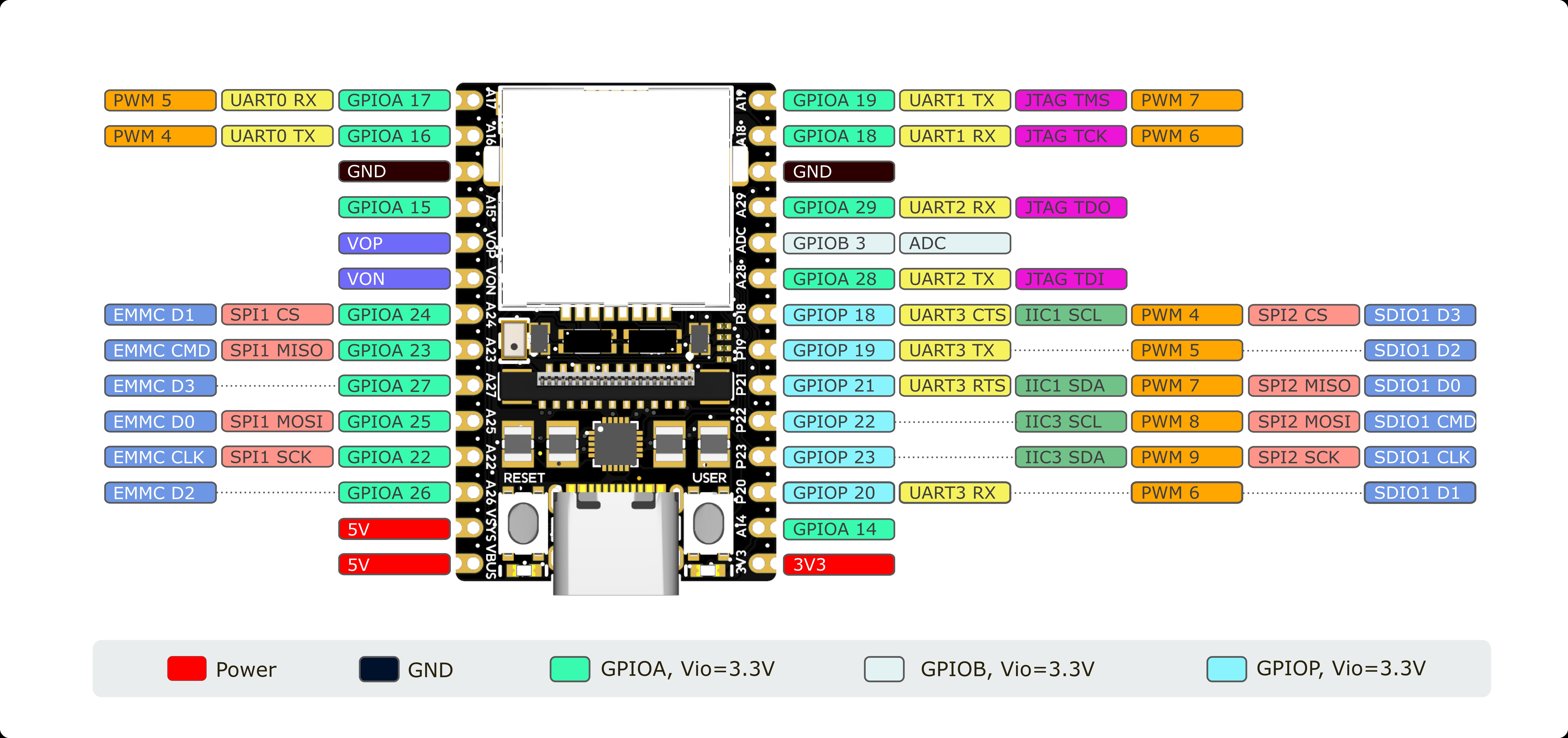 |
On the silkscreen, for example, A19 is the pin name and PWM7 is the function name |
| MaixCAM-Pro | 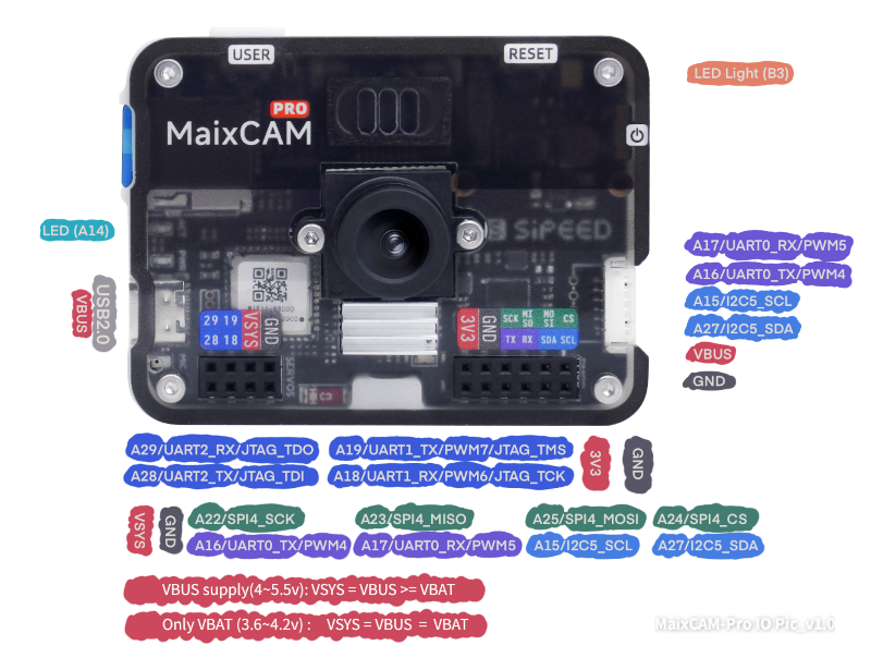 |
The first name, such as A19, is the pin name; the corresponding PWM7 is the function name |
| MaixCAM2 | 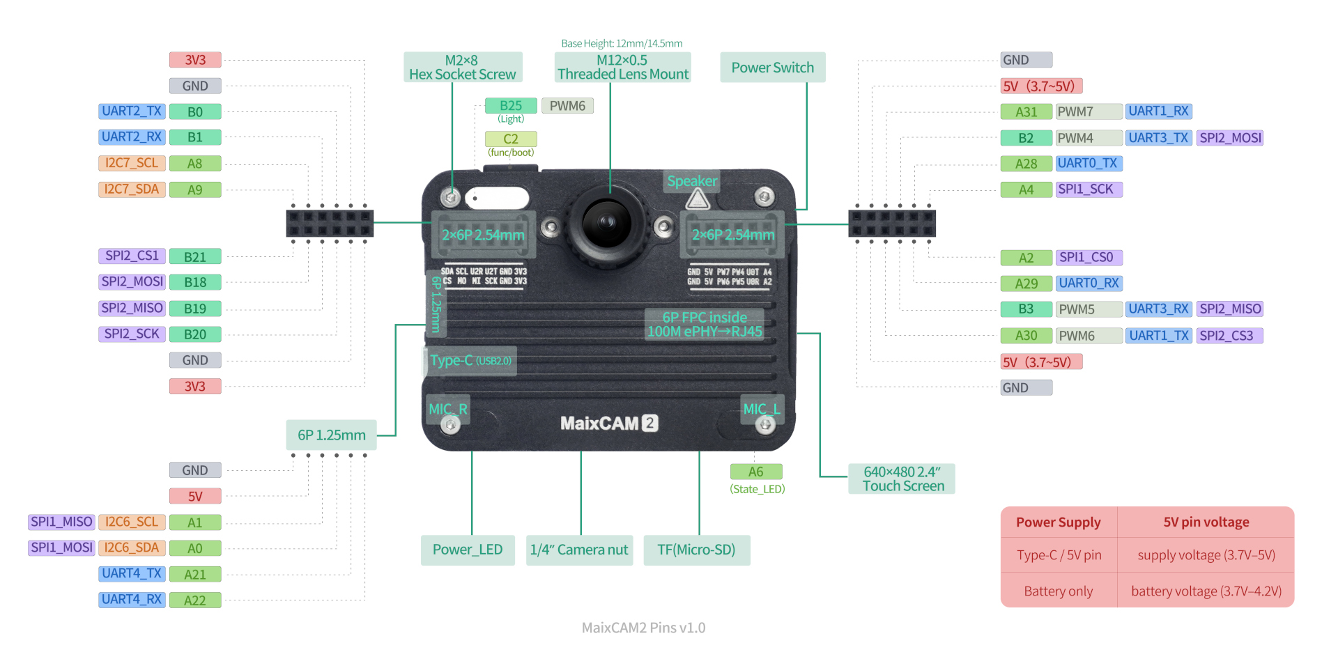 |
The first name, such as B25, is the pin name; the corresponding PWM6 is the function name |
Note that pins may be used for other purposes by default; it’s best to avoid those pins. See the pinmap documentation for details.
For example:
MaixCAM/MaixCAM-Pro: SinceWiFiuses all pins ofSDIO1,PWM4~9are not recommended for use.MaixCAM2: By default, 4 PWM pins can be used directly. The lighting LED can also be controlled byPWM6, but note thatPWM6can only be used for eitherA30or the lighting LED at one time, not both.
Using PWM in MaixPy to Control LED Brightness
Using the persistence of human vision, keeping the LED always on will make it brightest, while switching it on and off rapidly can control brightness—the longer the off-time proportion, the dimmer it appears.
from maix import pwm, time, pinmap, sys, err


# get pin and pwm number according to device id
device_id = sys.device_id()
if device_id == "maixcam2":
    pin_name = "B25" # LED light
    pwm_id = 6
else:
    pin_name = "A18" # A18 pin
    pwm_id = 6

# set pinmap
err.check_raise(pinmap.set_pin_function(pin_name, f"PWM{pwm_id}"), "set pinmap failed")


SERVO_PERIOD = 100000     # 100kHz 0.01ms

out = pwm.PWM(pwm_id, freq=SERVO_PERIOD, duty=0, enable=True)

for i in range(100):
    print(i)
    out.duty(i)
    time.sleep_ms(100)

for i in range(100):
    print(100 - i)
    out.duty(100 - i)
    time.sleep_ms(100)
Using PWM in MaixPy to Control a Servo
Controlling the servo angle is done by adjusting the duty cycle—different duty cycles correspond to different angles. Refer to the servo’s documentation.
Here, we control the servo to rotate from the minimum angle to the maximum angle and then back to the minimum:
from maix import pwm, time, pinmap, err

SERVO_PERIOD = 50     # 50Hz 20ms
SERVO_MIN_DUTY = 2.5  # 2.5% -> 0.5ms
SERVO_MAX_DUTY = 12.5  # 12.5% -> 2.5ms


# get pin and pwm number according to device id
device_id = sys.device_id()
if device_id == "maixcam2":
    pin_name = "A31"
    pwm_id = 7
else:
    pin_name = "A19"
    pwm_id = 7

# set pinmap
err.check_raise(pinmap.set_pin_function(pin_name, f"PWM{pwm_id}"), "set pinmap failed")


def angle_to_duty(percent):
    return (SERVO_MAX_DUTY - SERVO_MIN_DUTY) * percent / 100.0 + SERVO_MIN_DUTY


out = pwm.PWM(pwm_id, freq=SERVO_PERIOD, duty=angle_to_duty(0), enable=True)

for i in range(100):
    out.duty(angle_to_duty(i))
    time.sleep_ms(100)

for i in range(100):
    out.duty(angle_to_duty(100 - i))
    time.sleep_ms(100)
More Examples
See MaixPy examples.
API Documentation
For more APIs, see the PWM API documentation