English
FAQ
Update history
| Date | Version | Author | Update content |
|---|---|---|---|
| 2023-09-12 | v0.1 | lxo |
|
The following lists some common problems according to the form of Q&A, please try to find a solution in the following if you find any problem when using it, if the above record doesn't solve your problem, you can try to ask the question in Community, reasonable questions will be answered by the technical staff for you.
General Question
Q:There are some functional defects when using the logic analyzer/DAPLink/JLink/serial port module.
A:Please try to find and resolve your issue first in the Q&A section. If the problem persists, click here to update the firmware and try again.
Q:The LED doesn't change after pressing the button?
A:Check that the interval between key presses is not less than 100ms, otherwise it may cause the module to enter boot mode and you will see that LED no longer change. If this occurs, re-power up the module to restore it
Logic Analyzer
Q: After clicking "run", the prompt "device closed but should be open."
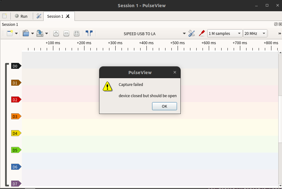
A:This may be the result of unstable contact that causes the device to disconnect, try to re-plug the device and then reconnect it to solve the problem.
Q:When using 8-channel sampling, it was found that waveforms also appeared when the D7 channel was not connected.
A:This is a problem to be solved, but this problem will not affect the sampled waveforms, and the waveform can still be acquired normally after connecting an external signal to the D7 channel.
Q:When sampling waveforms, the waveforms in the display window do not match the actual waveforms.
A:Make sure that you connect the GND wire of the logic analyser to the GND of the target device, and make sure that the GND wire is as close as possible to the location of the point to be measured. Be aware that even at a distance of 1cm, there may be many components in between that can interfere with the signal, so even 1cm closer is likely to give better signal quality.
Q:Logic analyser can't sample for long periods of time
A:There are multiple situations:
Situation 1: Sampling time is very small due to incorrect setting of sampling points and sampling rate, sampling time (unit:s) = sampling points/sampling rate, please make sure that the sampling points and sampling rate are set correctly.
Situation 2: Effect from PC performance. As PulseView needs to use a lot of USB bandwidth, but if the PC performance is poor at this time, it will also result in shorter sampling times.
Situation 3: If everything is fine, check if the number of sampling points is set too large, resulting in a memory overflow that prevents sampling
DAPLink
Q:MDK can't find DAPLink device
A:It is possible that the MDK version is too low, and a low version of MDK may not be able to recognise DAPLink (the MDK version used for testing in this article is V5.38). If the MDK version is too low to recognise DAPLink, if you don't want to upgrade the version, you can refer to the method here to update the debug driver of CMSIS-DAP.
Q:The serial port function in DAPLink mode does not work properly and messages are echoed back
A:Please refer here to update the firmware to the latest version before trying again
Q:DAPLink error while burning firmware:Connection refused due to device mismatch!

A:It may be caused by the mismatch between the chip package and the actual chip. For example, MDK uses STM32F103 configuration, but the actual chip is CS32F103, the IDCODE of STM32F103 is 0x1B10417, and the IDCODE of CS32F103 is 0x2BA01477, which causes a device mismatch and refuses to connect. The solution is to find and install the software package for the actual chip, and since there are so many packages, please find the download method by yourself.
CKLink
None
Serial Module
Q:The serial terminal cannot open the serial port.
A:Try using a different serial terminal. For Windows, you can try using XCOM, and for Linux, you can try using Minicom.