English
Tang Nano 9K
Introduction
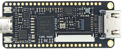
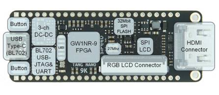
The Tang Nano 9K, powered by Gowin's GW1NR-LV9QN88PC6/I5 FPGA chip, is a versatile and feature-rich development board. It features several often used connectors, including HDMI, RGB screen, and SPI screen interfaces, as well as a 32Mbit SPI flash and six LEDs. It has 8640 LUT4 logic units, an onboard 27MHz clock and 2 PLLs meaning, as well as basic FPGA designs, it can also be used for full risc-v softcores such as PicoRV.
Comparison
Tang Nano 9K is the 5th product of Sipeed Tang series. Several Tang FPGA products are compared in the table below, if you need a more feature-rich board consider the Tang Nano 20K.
| Model | Tang Nano 1K | Tang Nano 4K | Tang Nano 9K |
|---|---|---|---|
| Appearance |  |
 |
 |
| Logic Units (LUT4) | 1152 | 4608 | 8640 |
| Hard core processor | / | Cortex m3 | / |
| Crystal oscillator | 27MHZ | 27MHZ | 27MHZ |
| Display interface | RGB screen interface | HDMI | HDMI, RGB screen interface, SPI screen interface |
| Camera | / | Support OV2640 | / |
| External SPI FLASH | Reserved pads only | 32Mbits SPI flash | 32Mbits SPI flash |
| TF card slot | / | / | Yes |
| Debugger | Onboard USB-JTAG | Onboard USB-JTAG | Onboard USB-JTAG & USB-UART |
Specifications
Indepth specifications of the tang nano 9k.
| Item | value |
|---|---|
| Logic units(LUT4) | 8640 |
| Registers(FF) | 6480 |
| ShadowSRAM SSRAM(bits) | 17280 |
| Block SRAM BSRAM(bits) | 468K |
| Number of B-SRAM | 26 |
| User flash(bits) | 608K |
| PSRAM(bits) | 64M |
| 18 x 18 Multiplier | 20 |
| SPI FLASH | 32M-bit |
| Number of PLL | 2 |
| Display interface | HDMI interface, SPI screen interface and RGB screen interface |
| Debugger | Onboard BL702 chip provides USB-JTAG and USB-UART functions for GW1NR-9 |
| IO | • support 4mA、8mA、16mA、24mA other driving capabilities • Provides independent Bus Keeper, pull-up/pull-down resistors, and Open Drain output options for each I/O |
| Connector | TF card slot, 2x24P 2.54mm Header pads |
| Button | 2 programmable buttons for users |
| LED | Onboard 6 programmable LEDs |
On-board Function block
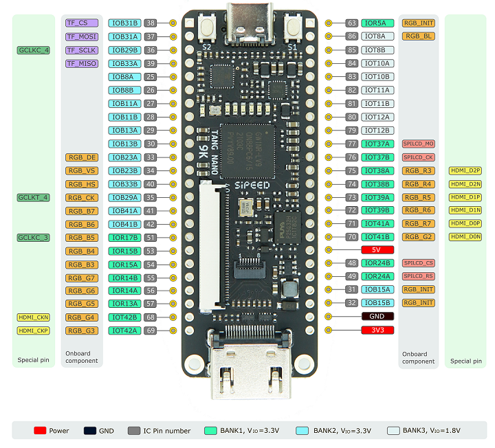
Pinmap
| Usage | FPGA | MCU | FPGA+MCU |
|---|---|---|---|
| Language | Verilog HDL/Verilog | C/C++ | Verilog HDL/Verilog , C/C++ |
| Introduction | verify HDL design | After flashing the softcore bitstream, this board can be used as a normal microcontroller unit |
After flashing the softcore bitstream, it can be used as two chips |
| User | Beginner,FPGA developer | RISC-V developers,Cortex-M developers | Senior engineer |
Getting Started
Download User Guide: Access all necessary PDF documents by downloading our comprehensive user guide package.
Install IDE & License Configuration: Set up your Integrated Development Environment (IDE) and configure your license by following this guide.
Software User Guide: Refer to the "SUG100-2.6E_Gowin Software User Guide.pdf" in the downloaded package for detailed software instructions.
LED Tutorial: A simple project to get you acquainted to FPGAs and the tangnano9k.
- Verilog Code Standards: It's crucial to adhere to good coding practices.
- Recommended Reading:
- SUG949-1.1E_Gowin HDL Coding User Guide.pdf
- UG286-1.9.1E_Gowin Clock User Guide.pdf
These, and other important, documents are available at our Download Station.
Online Resources: We recommend two excellent learning sites for Verilog: HDLBITs and ASIC World's Verilog Page.
RGB Screen Tutorial: Follow this step-by-step guide for setting up a 5-inch RGB screen display. If you encounter difficulties, refer to our 9K examples adapted for 9K + 5-inch screens.
- Screen Wiring Note: Ensure correct alignment of the 1-pin silk screen on the connector with the 1-pin of the cable.
- Key Documents for Reference:
- rPLL IP core reference: Navigate to Tools > IP Core Generator > Hard Module > CLOCK > rPLL.
- SUG284-2.1E_Gowin IP Core Generator User Guide.pdf (Page 28)
- Datasheet of 5-inch Screen
Examples in the source code repository includes a PicoRV softcore and a HDMI display example, among other examples.
Reference and Examples
You can access several example projects on our Examples Page.
Hardware Resources
- Access all necessary hardware files at Hardware Files.
Attention and Best Practices
Support and Community: For assistance, join our Telegram group (t.me/sipeed) or contact us on Twitter (@SipeedIO). You can also leave a message below.
Troubleshooting: If you encounter any issues, consult our Tang Questions page first.
Avoid using JTAG, MODE0/1, and DONE pins unless necessary. For details, refer to SUG100-2.6E_Gowin Software User Guide.pdf.
Static Electricity Precautions: Always discharge static electricity before handling the PCBA to prevent damage.
GPIO Voltage Compliance: Ensure that the actual working voltage of GPIOs does not exceed their rated value as indicated in the schematic. Exceeding these limits can cause permanent damage to the PCBA.
FPC Cable Connection: When connecting FPC flexible cables, ensure that the cable is fully inserted into its base without any offset.
Avoid Short Circuits: Prevent liquids or metals from coming into contact with the component pads on the PCBA while it's operating, as this could cause a short circuit and damage the PCBA.
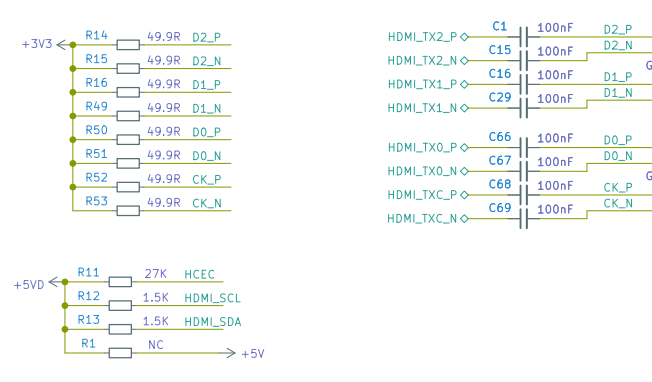
Handling Multiplexed IO and HDMI Ports: Be aware that the HDMI IO ports are pulled up. When using IOs routed to pin headers, they may not operate as intended.