English
Peripheral Usage
Update history
| Date | Version | Author | Update content |
|---|---|---|---|
| 2024-07-30 | v1.0 | zepan |
|
SoC related
CPU operating frequency
sudo cat /sys/devices/system/cpu/cpu*/cpufreq/cpuinfo_cur_freq
Unit in KHz
Please note that the system comes with a temperature control strategy. When the system is too idle or the temperature is too high, the frequency will be reduced. Please maintain good heat dissipation to keep the CPU below 60 degrees Celsius for optimal performance.
Chip temperature
cat /sys/class/thermal/thermal_zone0/temp
The unit is 0.001 degrees Celsius
UART
System serial port
The system serial port of LicheePi 3A is UART0, which is led out in the side pins.
You can use a USB to serial module to connect the serial ports, namely 'U0-RX' and 'U0-TX', paying attention to cross connection and GND connection.
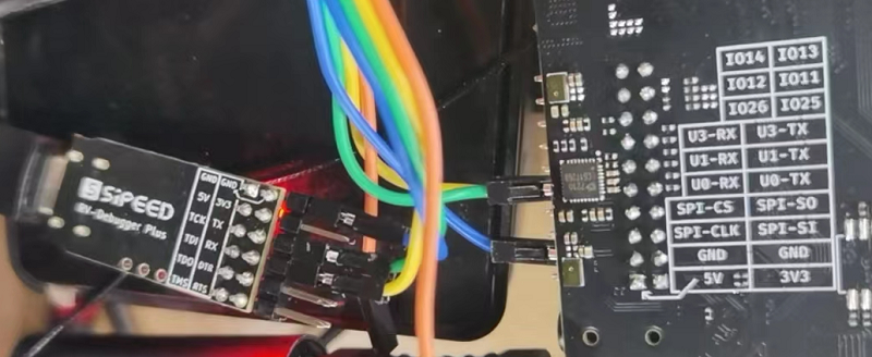
After the connection is completed, you can use the serial port tool for communication. For Windows, XShell and MOBaterm are recommended, and for Linux, Minicom is recommended`
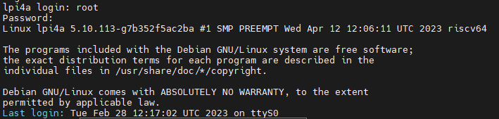
Set the serial port baud rate to '115200' to log in and perform command operations under the serial port terminal:
Note: After just connecting, you can press a few Enter keys to check for any response. If there is no response, check the wiring or serial port configuration
General serial port
The side pins of LicheePi 4A also lead out UART1, which can also be operated.
Only UART1 is enabled in the default image, and other serial ports may need to reconfigure device tree operations.
View serial devices
ls /dev/ttyS*
Check the baud rate and other information of the serial port
stty -F /dev/ttyS1 -a
Set serial port baud rate and data mode
stty -F /dev/ttyS1 ispeed 115200 ospeed 115200 cs8
View serial port data
cat /dev/ttyS1
Send serial port data
echo "12345" > /dev/ttyS1
Other methods
Users can also use 'microcom' or the pyserial library for serial port operations. Please search for relevant information and use it yourself.
I2C
There are multiple I2C devices (I2C0/2/5/6) on LicheePi 3A, with I2C2 connected to a codec chip; I2C5 is connected to the IO expansion chip and also to the pins; I2C6 connects the touch screen and IO expansion chip.
Here we use i2c tools for i2c verification operations. The default image does not have i2c tools installed. Please use apt to install them first
apt install i2c-tools
List all I2C buses:
root@k1 :~# i2cdetect -l
i2c-0   i2c             spacemit-i2c-adapter                    I2C adapter
i2c-2   i2c             spacemit-i2c-adapter                    I2C adapter
i2c-5   i2c             spacemit-i2c-adapter                    I2C adapter
i2c-6   i2c             spacemit-i2c-adapter                    I2C adapter
i2c-8   i2c             spacemit-i2c-adapter                    I2C adapter
Detecting devices on the I2C bus, it can be seen that the I2C address of PCA9557PW is 0x18, which is consistent with the schematic diagram:
sipeed@lpi4a :~$ sudo /sbin/i2cdetect -r -y 5
0  1  2  3  4  5  6  7  8  9  a  b  c  d  e  f
00:                         -- -- -- -- -- -- -- --
10: -- -- -- -- -- -- -- -- UU -- -- -- -- -- -- --
20: -- -- -- -- -- -- -- -- -- -- -- -- -- -- -- --
30: -- -- -- -- -- -- -- -- -- -- -- -- -- -- -- --
40: -- -- -- -- -- -- -- -- -- -- -- -- -- -- -- --
50: -- -- -- -- -- -- -- -- -- -- -- -- -- -- -- --
60: -- -- -- -- -- -- -- -- -- -- -- -- -- -- -- --
70: -- -- -- -- -- -- -- --
In addition, 'i2cdump' can be used to dump all registers at the specified i2c address, 'i2cget' can be used to read the specified register value at the specified i2c address, and 'i2cset' can be used to write the specified register value at the specified i2c address.
However, as the IO expansion chip has already been used by the kernel, these commands cannot be directly used for verification. Users can connect external devices to I2C2 for verification.
SPI
LicheePi3A has reserved two SPI paths, one is the SPI Flash pad with empty backside, and the other is the SPI on the pin.
Commonly used ioctl commands for SPI:
-SPI_SOC_maSSAGE: Used for sending and receiving SPI messages, can be used for reading and writing data, controlling devices, and other operations
-SPI_SOC_2R_MODE: Used to set the working mode of SPI devices, such as CPOL, CPHA, etc
-SPI_SOC_CD_MODE: Used to read the working mode of SPI devices
-SPI_SOC-WR_LSB_FIRST: Used to set the byte order of SPI devices, that is, whether the highest bit is transmitted first or the lowest bit is transmitted first
-SPI_SOC_SD_LSB_FIRST: Used to read the byte order of SPI devices
-SPI_SOC-WR_BITs_PER-WORD: Used to set the data bit width of SPI devices
-SPI_SOC-RD_BITs_PER-WORD: Used to read the data bit width of SPI devices
-SPI_SOC-WR_MAX_SPEED_HZ: Used to set the maximum clock frequency of SPI devices
-SPI_SOC_SD_MAX_SPEED_HZ: Used to read the maximum clock frequency of SPI devices
-SPI_SOC-WR_MODE32: Used to set the 32-bit mode of SPI devices, such as CPOL, CPHA, etc
-SPI_SOC_CD_MODE32: Used to read the 32-bit mode of SPI devices
The above are some commonly used ioctl commands for SPI devices, which can be used to configure and control various parameters of SPI devices.
To turn on/off SPI devices:
int open(const char *pathname, int flags);
int close(int fd);
Header files to be referenced:
#include<fcntl.h>
#include<unistd.h>

```c
#include <stdint.h>
#include <unistd.h>
#include <stdio.h>
#include <stdlib.h>
#include <string.h>
#include <getopt.h>
#include <fcntl.h>
#include <sys/ioctl.h>
#include <linux/types.h>
#include <linux/spi/spidev.h>

#define DATA_NUM 2
#define CHECK(ret, str) if (ret < 0) {printf("%s\r\n", str); return ret;}
static uint8_t bits = 8;
static uint32_t speed = 1000000; // 1M Hz
static int mode = 0;

int main(int argc, char *argv[]) {
    int ret, fd;
    fd = open("/dev/spidev2.0", O_RDWR);
    CHECK(fd, "can't open device");
    mode = SPI_MODE_0 | SPI_CS_HIGH;
    ret = ioctl(fd, SPI_IOC_WR_MODE32, &mode);
    CHECK(ret, "can't set spi mode");
    ret = ioctl(fd, SPI_IOC_RD_MODE32, &mode);
    CHECK(ret, "can't get spi mode");

    ret = ioctl(fd, SPI_IOC_WR_BITS_PER_WORD, &bits);
    CHECK(ret, "can't set bits per word");
    ret = ioctl(fd, SPI_IOC_RD_BITS_PER_WORD, &bits);
    CHECK(ret, "can't get bits per word");

    ret = ioctl(fd, SPI_IOC_WR_MAX_SPEED_HZ, &speed);
    CHECK(ret, "can't set max speed hz");

    ret = ioctl(fd, SPI_IOC_RD_MAX_SPEED_HZ, &speed);
    CHECK(ret, "can't get max speed hz");

    printf("spi mode: %d\n", mode);
    printf("bits per word: %d\n", bits);
    printf("max speed: %d Hz (%d KHz)\n", speed, speed/1000);

    uint8_t tx[] = {0x11, 0x22};
    uint8_t rx[DATA_NUM] = {0};

    struct spi_ioc_transfer tr = {
        .tx_buf = (unsigned long)tx,
        .rx_buf = (unsigned long)rx,
        .len = DATA_NUM,
        .delay_usecs = 0,
        .speed_hz = speed,
        .bits_per_word = bits
    };

    ret = ioctl(fd, SPI_IOC_MESSAGE(1), &tr);
    CHECK(ret, "can't send spi message");

    printf("tx: %.2X %.2X\r\n", tx[0], tx[1]);
    printf("rx: %.2X %.2X\r\n", rx[0], rx[1]);

    close(fd);

    return ret;
}
USB
LPi3A has 4 USB 3.0 ports, which can be plugged into a USB device to work. It will not be repeated here.
Note that if you are using the LPi4A motherboard, the differences in the motherboard may cause the USB A port under the default image to be unusable. For the first use, you need to connect to the serial port or network, enter the device terminal, and replace the DTB
Under/boot/spacemit/6.1.15/, overwrite k1-x_lpi3a_4a.dtb with k1-x_lpi3a.dtb and restart to use USB
ETH
LicheePi4A has dual gigabit Ethernet ports, with Eth0 also having PoE functionality.
PoE
The Ethernet 0 interface of LicheePi 4A has PoE function and can be powered through PoE.
The PoE power supply module needs to be purchased by oneself, with a specification of 5V voltage and 35.6mm length, which can be obtained by searching for the keyword "5V PoE pin".
When the visual direction is facing the "POE POWER" label, the four pins on the left of the pin are defined from left to right as VA1, VA2, VB1, VB2, and GND, 5VIN on the right.
Speaker Audio
The LicheePi 4A has two analog silicon microphones using ES7210 CODEC, as well as an onboard speaker and stereo headphones using ES8156 CODEC.
Note: The onboard speakers and stereo headphones use a mutually exclusive design. After inserting the headphones, the audio output automatically switches to the headphones, and the onboard speakers become disabled.
Easy recording and playback tests can be conducted using APLay and ARECord, please note that the onboard speaker is for the right channel.
#!/ bin/bash
echo "Play Test Audio"
aplay -Dhw:1,0 disco48.wav
You can also use Alsa related tools, such as' Alsamixer ', to adjust the volume and perform other operations.
Please note that currently only 48KHz audio playback is supported. The recording function is currently under development.
MIPI CSI
The LicheePi 3A has two camera interfaces on the back, the 24Pin interface is compatible with the LPi4A's 2-lane camera interface, and the 22Pin interface is compatible with the Raspberry Pi's 22Pin 4-lane camera interface.
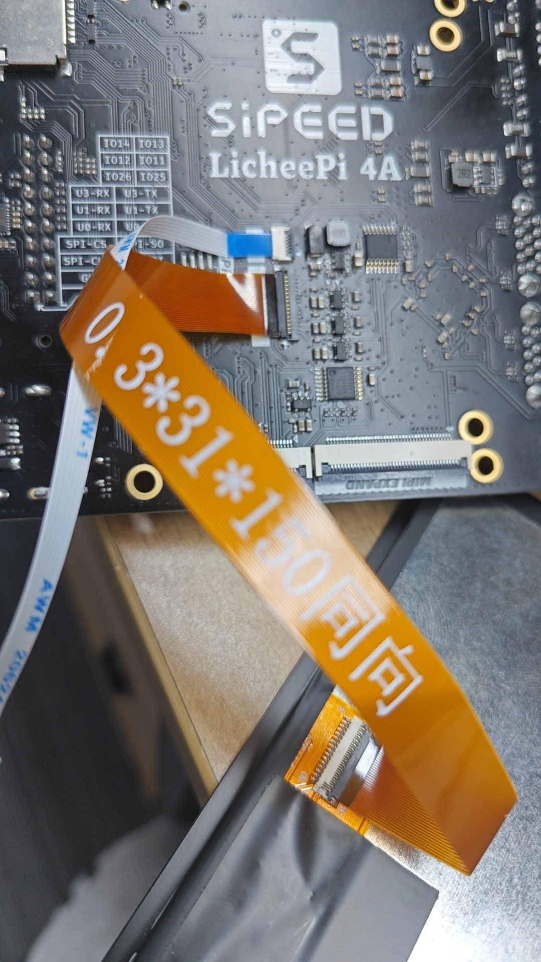
MIPI DSI
LicheePi 3A has MIPI DSI0 interface, supports 1080P video output, and can be optionally equipped with a 10.1-inch 1280x800 touch screen.
The connection method is shown in the following figure. Both FPC ribbon cables are bottom connected (with the metal contact at the end of the cable facing downwards). When connecting the touch screen adapter board, attention should be paid to the direction. Confirm that the ToLPi4A end is connected to the LPi4A touch ribbon cable, and the ToLcdTP end is connected to the screen:
Schematic diagram of metal contact surface of flexible cable:
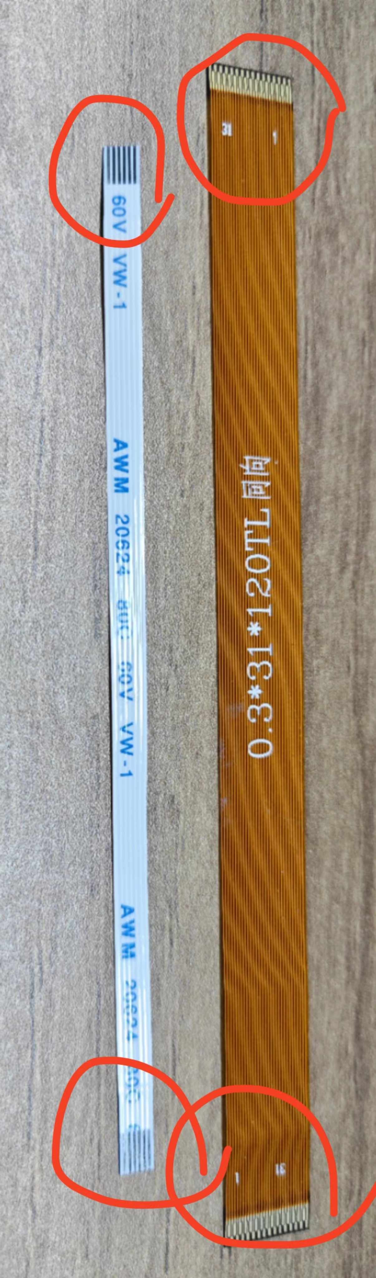
Note that before connecting, first pull up the black flip cover on the interface used to fix the cable, confirm that it is connected, and then unplug it.
Touch screen ribbon cable connection:
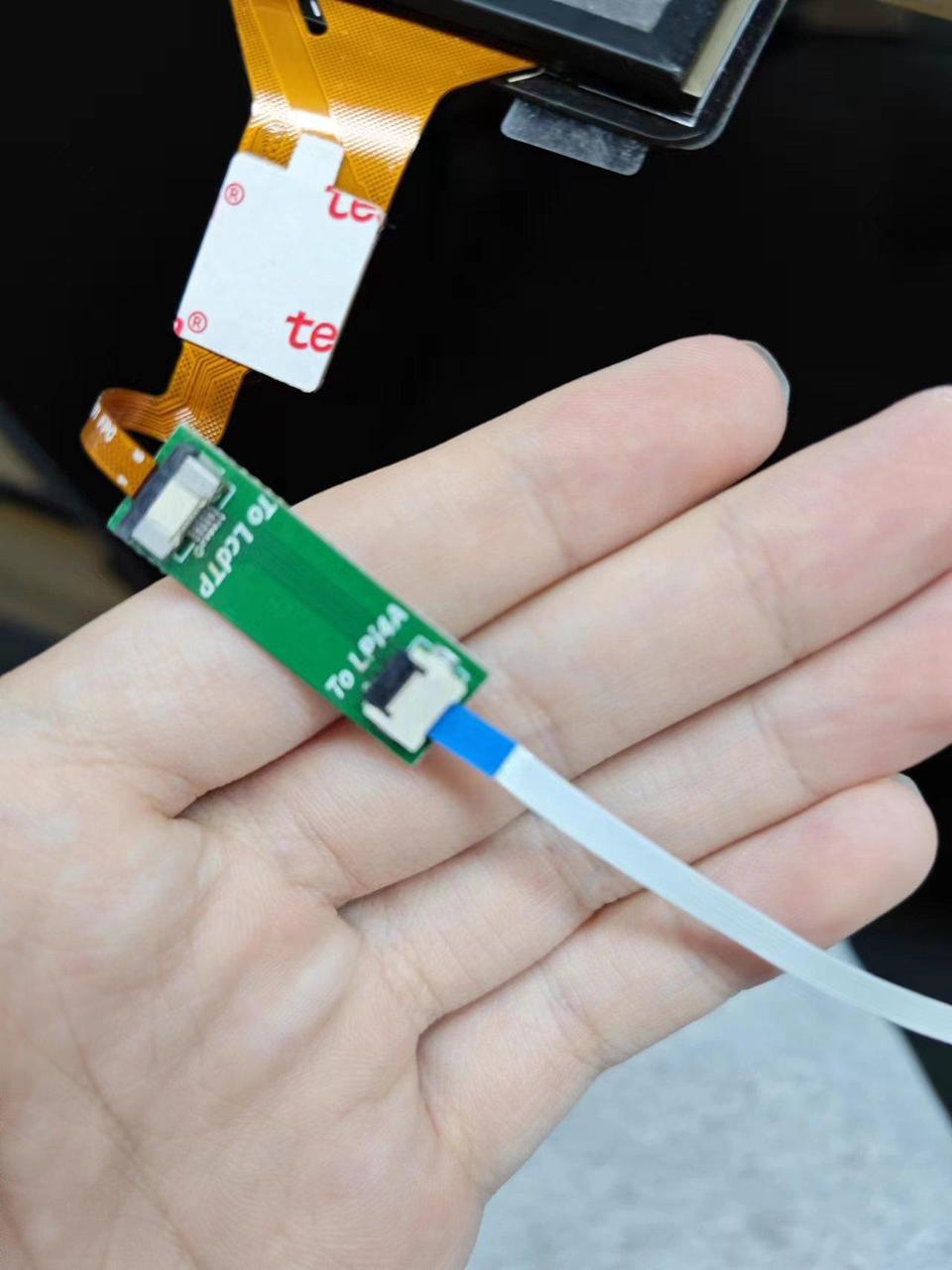
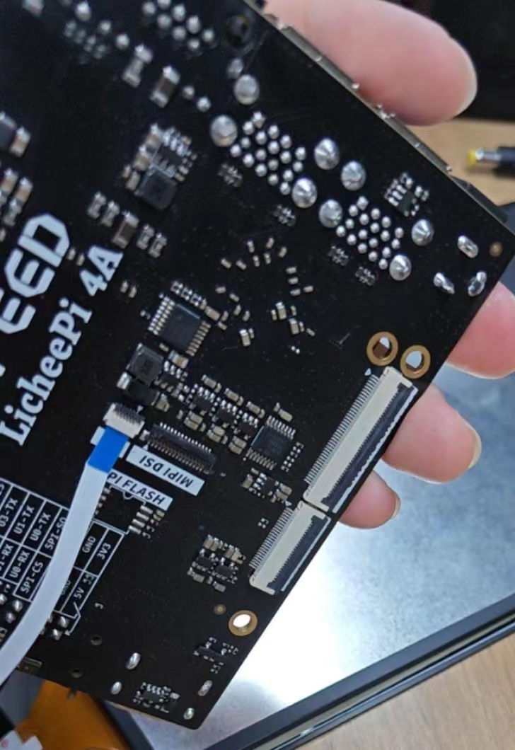
MIPI screen ribbon cable connection:
After confirming that the connection is correct, use the firmware (k1-x_lpi3a_lcd. dtb) that supports MIPI screens, and you can see the MIPI screen display upon booting up.
JTAG
The JTAG interface of K1 is multiplexed with TF card signals and can be connected using TF to JTAG small boards.
GPU
The following command can be used to view the real-time status of the GPU:
sudo watch cat /sys/kernel/debug/pvr/status