English
MaixSense-A010
Product description
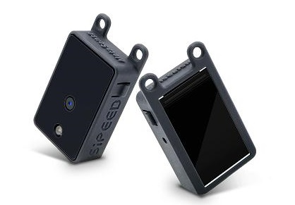
MaixSense-A010 is an extremely cost-effective 3D sensor module composed of BL702 + OPNOUS 100x100 TOF launched by Sipeed, which supports a maximum resolution of 100x100 and 8-bit precision, and comes with a 240x135 pixel LCD display to preview the depth map after colormap in real time.
Data summary
Hardware information:Click to download
Product unpacking guide
Preparation
MaixSense-A010 Uses the serial port protocol to provide interfaces and transmit data.
The physical interfaces we provide include type-c (virtual serial port) and 1.0mm 4pin motherboard (UART), which can obtain depth map data for integration.
Product wiring instructions
After connecting to the computer through the type-c interface, it can identify /dev/ttyUSBx (Linux) or COMx (Windows).
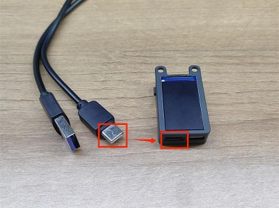
The usb2ttl module can also be used to connect the 4-PIN bus according to the hardware pin diagram (device screen face down).
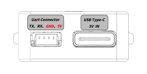
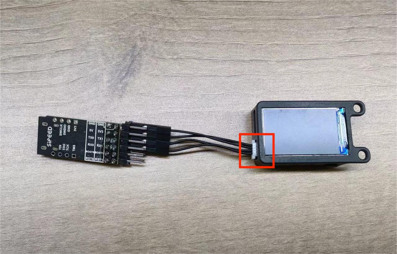
| MS-A010 | TX | RX | GND | 5V |
| usb2ttl 模块 | RX | TX | GND | 5V |
Power-up preview
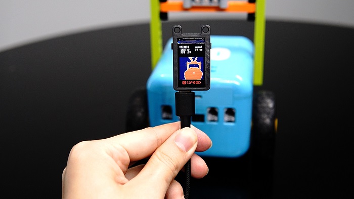
Button function: "Next" on the left and "Switch" on the right.
Screen display: the + word in the center of the screen is the ranging point, and the top right will display real-time xx cm on behalf of the distance ranging. If there is a large area of objects near the lens, "block!" will be displayed on the right of the screen. In other cases open!.
After the device is connected to the power supply, you can preview the depth pseudo-color map in real time on the built-in LCD screen of the device.
PC side preview interaction
Install COMTOOL on the upper computer before previewing and modifying the Settings on the PC.
Windows system:Click to download
Linux system:Users need to compile/click to jump
Note: Windows 7 and below systems need to install the driver, you can go to the FTDI official website to download.
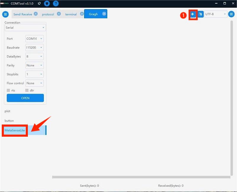
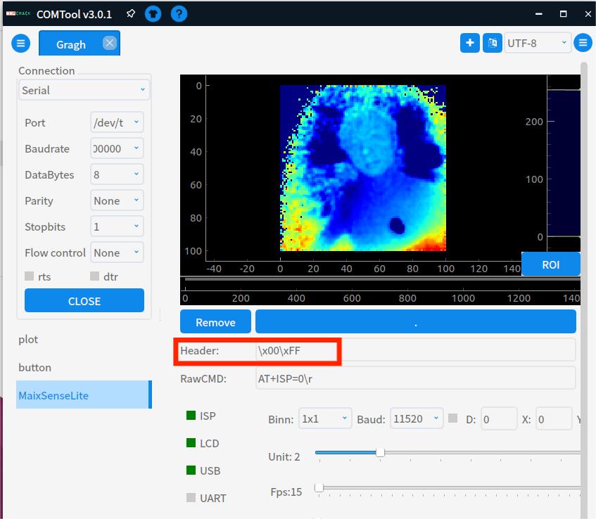
Open the COMTOOL software and select the Graph interface. If there is no Graph above the software, you can add a Graph at the + sign in the upper right corner. If the middle part is blank after creation, double-click MaixSenseLite in the lower left corner
Select a small Port and baud rate in the left port (choose any high baud rate), click open and check USB to receive a large amount of data. Connected will be displayed in the lower left corner.
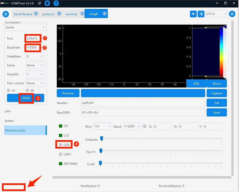
Set the Header to \x00\xFF to correctly parse the image data and observe the depth map to intuitively feel the depth on the 2D flat image.
Comtool configuration instructions
Comtool configuration control description of the host computer
- Header:et the identification header.
- RawCMD:User can send commands manually (USB and UART serial ports behave the same).
- ISP:start stop.
- LCD:display the lcd screen on and off.
- USB:serial port transmission depth map on and off.
- UART:serial port transmission depth map on and off.
- ANTIMMI:Automatic anti-multi-machine interference is turned on and off (susceptible to interference, the effect of turning off is better)
- Binn:pull down to set BINNING, Baud to set UART baud rate.
- X, Y:coordinates:When the checkbox to the left of D is on, the (x,y) distance from the camera is displayed.
- Unit:sets the quantization unit:16-bit quantization to 8-bit, the scale is reduced, if the setting is too small, only very close images can be seen clearly.
- FPS:Set the output frame rate (it should not be too high, set it reasonably according to the performance of the docking device, reducing the frame rate can reduce the amount of transmitted data)
- Ev:Exposure gap control (leftmost represents AE, others are fixed exposure time)
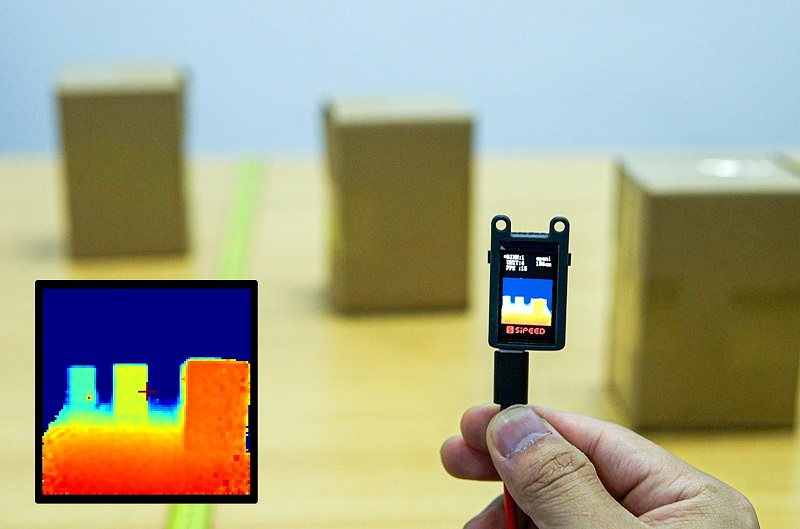
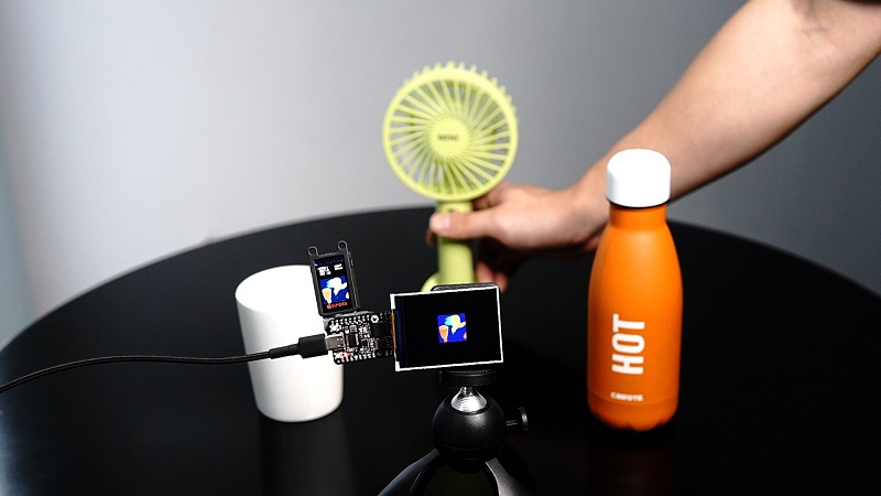
Case:Measure Objects Distance
The distance between the objects is placed to form the difference in depth value. After the module captures the difference, it displays a warm and cold color, a warm color when the distance is close, and a cool color when the distance is far.
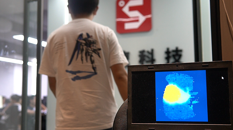
Case:Passengers Flow Statistical
Real-time, high-precision, high-resolution monitoring of human flow and quickly statistical data.
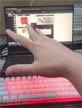
Case:Gesture Interaction
Realize super cool keyboard light follow,track the position of the hand in real time,and then map the keyboard light according to the position of the hand.
Case:Connect to MCUs
- MS-A010 has strong compatibility and is based on serial protocol. It can be connected to single-chip development boards such as K210 bit or linux development boards such as Raspberry Pi for secondary development.
- The k210 Bit development board is a member of the sipeed Maix product line. It is an AIOT development board designed based on the edge intelligent computing chip K210 (RISC-V architecture 64-bit dual-core) of Canaan Canzhi Technology.
MS-A010 external K210 bit source code acquisition
Secondary development:Serial protocol
Please refer to the above case: MS-A010 external K210 bit
Host USB source code acquisition
MS-A010 Secondary Development Manual:Click to view
Secondary development:Access ROS
Access ROS1
1. Preparations
First, prepare the applicable environment: Linux system.
You can use the virtual machine virtual box or vmware.
2. Install and run
ROS Access Package: Click to download.
# Unzip sipeed_tof_ms_a010.zip and enter the directory
cd ros1
source /opt/ros/*/setup.sh
catkin_make
source devel/setup.sh
rosrun sipeed_tof_ms_a010 a010_publisher _device:="/dev/ttyUSB0"
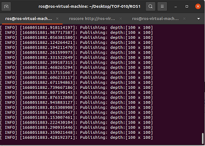
# After that, the terminal will continue to refresh and display [sipeed_tof]: Publishing, that is, it works normally
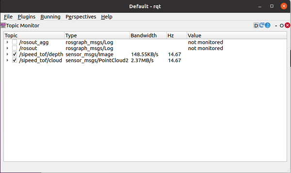
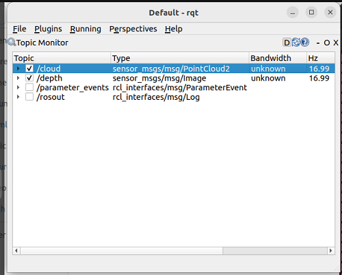
3. You can view the frame rate in RQT
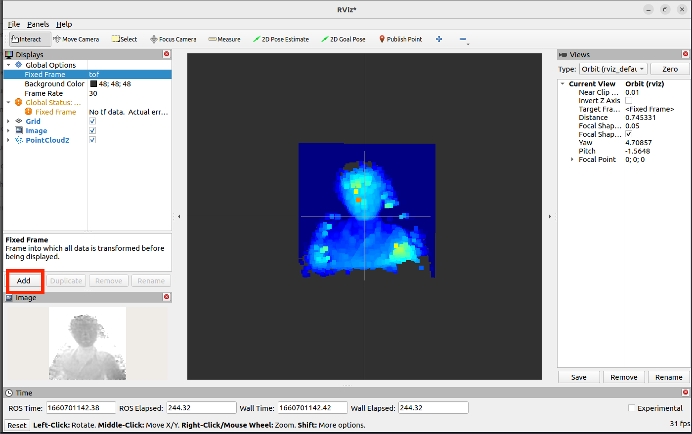
4. RVIZ2 Preview
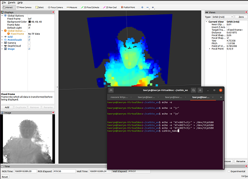
After opening rviz2, in the lower left corner of the interface Add->By topic->PointCloud2 or /depth ->Image Add ->Display/Global Options/Fixed Frame needs to be modified to tof, the point cloud can be displayed normally. According to the added content, Image will be displayed on the left and the point cloud will be displayed in the middle.
Access ROS2
1. Preparations
First, prepare the applicable environment: Linux system.
You can use the virtual machine virtual box or vmware.
If your environment also has ROS1 installed, ROS2 will need to be used with the correct version.
ls /opt/ros
ros@ros-virtual-machine:~/Desktop$ ls /opt/ros
noetic  rolling
2. Install and run
We provide an access package for ROS2, which users need to compile and install on a system running ROS2.
ROS Access Package:Click to download.
#Unzip sipeed_tof_ms_a010.zip and enter the directory
cd ros2
source /opt/ros/*/setup.sh
colcon build #If you are prompted that colcon is missing, you need sudo apt install python3-colcon-ros
source install/setup.sh
ros2 run sipeed_tof_ms_a010 publisher --ros-args -p device:="/dev/ttyUSB0"
# After that, the terminal will continue to refresh and display [sipeed_tof]: Publishing, that is, it works normally
3. RQT View frame rate
4. RVIZ2 Preview
After opening rviz2, in the lower left corner of the interface Add->By topic->PointCloud2 or /depth ->Image Add ->Display/Global Options/Fixed Frame needs to be modified to tof, the point cloud can be displayed normally. According to the added content, Image will be displayed on the left and the point cloud will be displayed in the middle.