English
MicArray 麦克风阵列
Summary
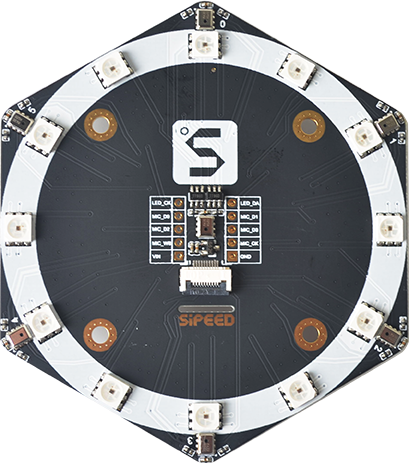
Sipeed microphone array consists of six microphones along the board and a center microphone. The 12 leds on the array board can be used to visualize and identify the location of the sound source, which can be used to do the sound source localization experiment.
Get it:
Product figure
Click me to download datasheet
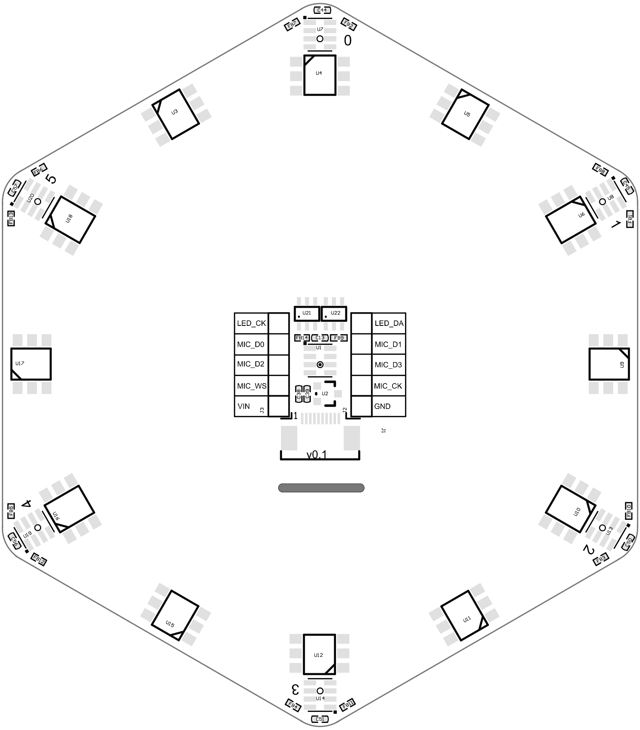
Click me to download schematic
Click me to download Assembly_drawing
Introduction
- MEMS microphone :7 MSM261S4030H0 make up the array
Click me to download datasheet of MSM261S4030H0 - Sensitivity : -26(dB,dBFS @1kHz 1Pa)
- Signal noise ratio : 57dB(20kHz bandwidth, A-weighted)
- Size :78.1*88.8mm
- LED :12 SK9822 LED make up the round led array
Click me to download datasheet of SK9822- Multiple leds are cascaded through dual signal lines
- 8 Bit(256 levels) for color adjustment,5 Bit(32 levels) for brightness adjustment
- Connector: Supports 2 x 5P 2.54mm terminals and a 10P 0.5mm FPC connector
Parameters
| Item | Parameter |
|---|---|
| Sound pressure level | 140 dB SPL |
| Sensitivity | -26(dB,dBFS @1kHz 1Pa) |
| Signal noise ratio | 57 dB (20kHz bandwidth,A-weighted) THD<1% (100dB SPL @1kHz S=Nom,Rload>2k ) |
| Clock frequency | 1.0-4.0Mhz(Normal mode) 150-800khz(Low energy mode) |
Pin definition
| Pin number | Pin name | Type | Pin description |
|---|---|---|---|
| 1 | VIN | VCC | Power input pin |
| 2 | GND | GND | Power ground pin |
| 3 | MIC_D0 | I/O | Serial data output from I²S interface of microphone 0 and microphone 1 |
| 4 | MIC_D1 | I/O | Serial data output from I²S interface of microphone 2 and microphone 3 |
| 5 | MIC_D2 | I/O | Serial data output from I²S interface of microphone 4 and microphone 5 |
| 6 | MIC_D3 | I/O | Serial data output from I²S interface of center microphone |
| 7 | MIC_WS | I/O | I²S interface serial data word selection |
| 8 | MIC_CK | I/O | I²S interface serial clock |
| 9 | LED_CK | I/O | LED serial clock |
| 10 | LED_DA | I/O | LED serial data |
Example code
Connection
Jumper Wire connection
| Microphone array | Pins on development board | Parameter in code |
|---|---|---|
| VIN | 3.3v/5v | —— |
| GND | GND | —— |
| LED_CK | I/O Port | sk9822_clk |
| LED_DA | I/O Port | sk9822_dat |
| MIC_D0 | I/O Port | i2s_d0 |
| MIC_D1 | I/O Port | i2s_d1 |
| MIC_D2 | I/O Port | i2s_d2 |
| MIC_D3 | I/O Port | i2s_d3 |
| MIC_WS | I/O Port | i2s_ws |
| MIC_CK | I/O Port | i2s_sclk |
Because of the FPIOA feature of K210, each peripheral can be mapped to any pin. Therefore, connect the I/O port in the above table with the pins with digital identification on your board. Those with special identification such as GND are not the so-called digital identification pins. After connecting the pins, you can see the description of the pins in the code below.
Burn firmware
Go to Download station to download firmware, download the default firmware described in Firmware naming instructions .
Micropython Code
from Maix import MIC_ARRAY as mic
import lcd

lcd.init()
mic.init()
#mic.init(i2s_d0=23, i2s_d1=22, i2s_d2=21, i2s_d3=20, i2s_ws=19, i2s_sclk=18, sk9822_dat=24, sk9822_clk=25)

while True:
    imga = mic.get_map()
    b = mic.get_dir(imga)
    a = mic.set_led(b,(0,0,255))
    imgb = imga.resize(160,160)
    imgc = imgb.to_rainbow(1)
    a = lcd.display(imgc)
mic.deinit()
According to the pin number of your own connection, init(i2s_d0=23, i2s_d1=22, i2s_d2=21, i2s_d3=20, i2s_ws=19, i2s_sclk=18, sk9822_dat=24, sk9822_clk=25). For example, if the MIC_D0 on the microphone array is connected to the pin labeled 25 on the K210 board, then the corresponding parameter in this code needs to be changed to i2s_d0=25, the other seven pins should be changed by the same way. Since configuration of everyone is different, there are no identical connection instructions for using jumper wires, modify the pin parameters individually, and don't forget to delete the comment before mic.init(...).(just delete #).
Make sure not use the pin which has been used for peripherals(Like camera pins or lcd pins should not bu used for this micarray pin), which will make amazing error.
C code
SK9822 driver codes
For reference only, source:github; It is recommended to copy the code to the computer local editor to view if analyzing the code.
sipeed_sk9822.c
#include "sipeed_sk9822.h"
define LED_NUM 12
define SK9822_DAT_SET()                 \

{                                    \
    gpiohs->output_val.bits.b27 = 1; \
}


define SK9822_DAT_CLR()                 \

{                                    \
    gpiohs->output_val.bits.b27 = 0; \
}


define SK9822_CLK_SET()                 \

{                                    \
    gpiohs->output_val.bits.b28 = 1; \
}


define SK9822_CLK_CLR()                 \

{                                    \
    gpiohs->output_val.bits.b28 = 0; \
}


static void sk9822_init(void)

{

    gpiohs_set_drive_mode(SK9822_DAT_GPIONUM, GPIO_DM_OUTPUT);

    gpiohs_set_drive_mode(SK9822_CLK_GPIONUM, GPIO_DM_OUTPUT);

    gpiohs_set_pin(SK9822_DAT_GPIONUM, 0);

    gpiohs_set_pin(SK9822_CLK_GPIONUM, 0);

}
void sk9822_send_data(uint32_t data)

{

    for (uint32_t mask = 0x80000000; mask > 0; mask >>= 1)

    {

        SK9822_CLK_CLR();

        asm volatile("nop");

        asm volatile("nop");

        asm volatile("nop");

        asm volatile("nop");

        asm volatile("nop");

        asm volatile("nop");

        asm volatile("nop");

        asm volatile("nop");

        asm volatile("nop");

        asm volatile("nop");

        asm volatile("nop");

        asm volatile("nop");

        asm volatile("nop");

        asm volatile("nop");

        asm volatile("nop");

        asm volatile("nop");

        asm volatile("nop");

        asm volatile("nop");

        asm volatile("nop");

        asm volatile("nop");

        asm volatile("nop");

        asm volatile("nop");

        asm volatile("nop");

        asm volatile("nop");

        // usleep(1);

        if (data & mask)

        {

            SK9822_DAT_SET();

        }

        else

        {

            SK9822_DAT_CLR();

        }

        SK9822_CLK_SET();

        asm volatile("nop");

        asm volatile("nop");

        asm volatile("nop");

        asm volatile("nop");

        asm volatile("nop");

        asm volatile("nop");

        asm volatile("nop");

        asm volatile("nop");

        asm volatile("nop");

        asm volatile("nop");

        asm volatile("nop");

        asm volatile("nop");

        asm volatile("nop");

        asm volatile("nop");

        asm volatile("nop");

        asm volatile("nop");

        asm volatile("nop");

        asm volatile("nop");

        asm volatile("nop");

        asm volatile("nop");

        asm volatile("nop");

        asm volatile("nop");

        asm volatile("nop");

        asm volatile("nop");

        asm volatile("nop");

        asm volatile("nop");

        asm volatile("nop");

        asm volatile("nop");

        asm volatile("nop");

        asm volatile("nop");

        asm volatile("nop");

        asm volatile("nop");

        // usleep(2);

    }

}
//32bit 0

void sk9822_start_frame(void)

{

    sk9822_send_data(0);

}
//32bit 1

void sk9822_stop_frame(void)

{

    sk9822_send_data(0xffffffff);

}
//1 1 1 1 gray | b | g | r

void sk9822_data_one_led(uint8_t gray, uint8_t r, uint8_t g, uint8_t b)

{

    uint32_t tosend;

gray &= 0x1f; //for make sure no error data in
tosend = ((0xe0 | gray) << 24) | (b << 16) | (g << 8) | r;
sk9822_send_data(tosend);

}
uint32_t sk9822_gen_data_one_led(uint8_t gray, uint8_t r, uint8_t g, uint8_t b)

{

    uint32_t tosend;

gray &= 0x1f; //for make sure no error data in
tosend = ((0xe0 | gray) << 24) | (b << 16) | (g << 8) | r;
return tosend;

}
//first color1, then msleep interval, then color2, last msleep interval

void sk9822_flash(uint32_t color1, uint32_t color2, uint32_t interval)

{

    uint8_t index;

color1 |= 0xe0000000;
color2 |= 0xe0000000;

sk9822_start_frame();
for (index = 0; index < LED_NUM; index++)
{
    sk9822_send_data(color1);
}
sk9822_stop_frame();
msleep(interval);

sk9822_start_frame();
for (index = 0; index < LED_NUM; index++)
{
    sk9822_send_data(color2);
}
sk9822_stop_frame();
msleep(interval);

}
static void arraymove(uint32_t array[], uint8_t len)

{

    uint8_t index;

    uint32_t tmp;

tmp = array[0];
for (index = 0; index < len - 1; index++)
{
    array[index] = array[index + 1];
}
array[len - 1] = tmp;

}

//呼吸

//跑马灯

//方位

void sk9822_horse_race(uint8_t r, uint8_t g, uint8_t b, uint32_t interval, uint8_t times)

{

    uint32_t led_frame[LED_NUM] = {0};

    uint8_t i, index;

for (index = 0; index < 12; index++)
{
    led_frame[index] = 0xff000000;
}

for (index = 0; index < 6; index++)
{
    // led_frame[index] = sk9822_gen_data_one_led((0xe0|(index*4)),r-40*index,g-30*index,b-20*index);
    led_frame[index] = sk9822_gen_data_one_led((0xe0 | (32 - index * 4)), r, g, b);
}

for (index = 0; index < times; index++)
{
    while (1)
    {
        sk9822_start_frame();
        for (i = 0; i < 12; i++)
        {
            sk9822_send_data(led_frame[i]);
        }
        sk9822_stop_frame();
        arraymove(led_frame, LED_NUM);
        msleep(interval);
    }
}

}
void sk9822_breath(uint8_t r, uint8_t g, uint8_t b, uint32_t interval)

{

    uint8_t index, cnt, dir;

uint32_t color = sk9822_gen_data_one_led(0xff, r, g, b);

cnt = 0;
dir = 1;

while (1)
{
    if (cnt >= 30)
    {
        dir = !dir;
        cnt = 0;
    }
    cnt++;
    color = sk9822_gen_data_one_led((0xe0 | (dir ? cnt : 31 - cnt)), r, g, b);
    sk9822_start_frame();
    for (index = 0; index < LED_NUM; index++)
    {
        sk9822_send_data(color);
    }
    sk9822_stop_frame();
    msleep(interval);
}

}
void sipeed_init_mic_array_led(void)

{

    sk9822_init();

    //flash 3 times

    sk9822_flash(0xffeec900, 0xffff0000, 200);

    sk9822_flash(0xffeec900, 0xff00ff00, 200);

    sk9822_flash(0xffeec900, 0xff0000ff, 200);

}
// void sipeed_calc_voice_strength(uint8_t voice_data[])

// {

//     uint32_t tmp_sum[12] = {0};

//     uint32_t led_color[12];

//     uint8_t i, index, tmp;
//     for (index = 0; index < 12; index++)

//     {

//         tmp_sum[index] = 0;

//         for (i = 0; i < voice_strength_len[index]; i++)

//         {

//             tmp_sum[index] += voice_data[voice_strength[index][i]];

//         }

//         tmp = (uint8_t)tmp_sum[index] / voice_strength_len[index];

//         led_brightness[index] = tmp > 15 ? 15 : tmp;

//     }

//     sk9822_start_frame();

//     for (index = 0; index < 12; index++)

//     {

//         led_color[index] = (led_brightness[index] / 2) > 1 ? (((0xe0 | (led_brightness[index] * 2)) << 24) | 0xcd3333) : 0xe0000000;

//         sk9822_send_data(led_color[index]);

//     }

//     sk9822_stop_frame();

// }
Micarray code
For reference only, source:github; It is recommended to copy the code to the computer local editor to view if analyzing the code.
Other information
More Usage
Go to bbs(Only Chinese) for more.
Question
This error occurs

Use other IO port.