

 English
 Translate
MicArray UAC Drive Board MA-USB8 — User Guide
Product overview
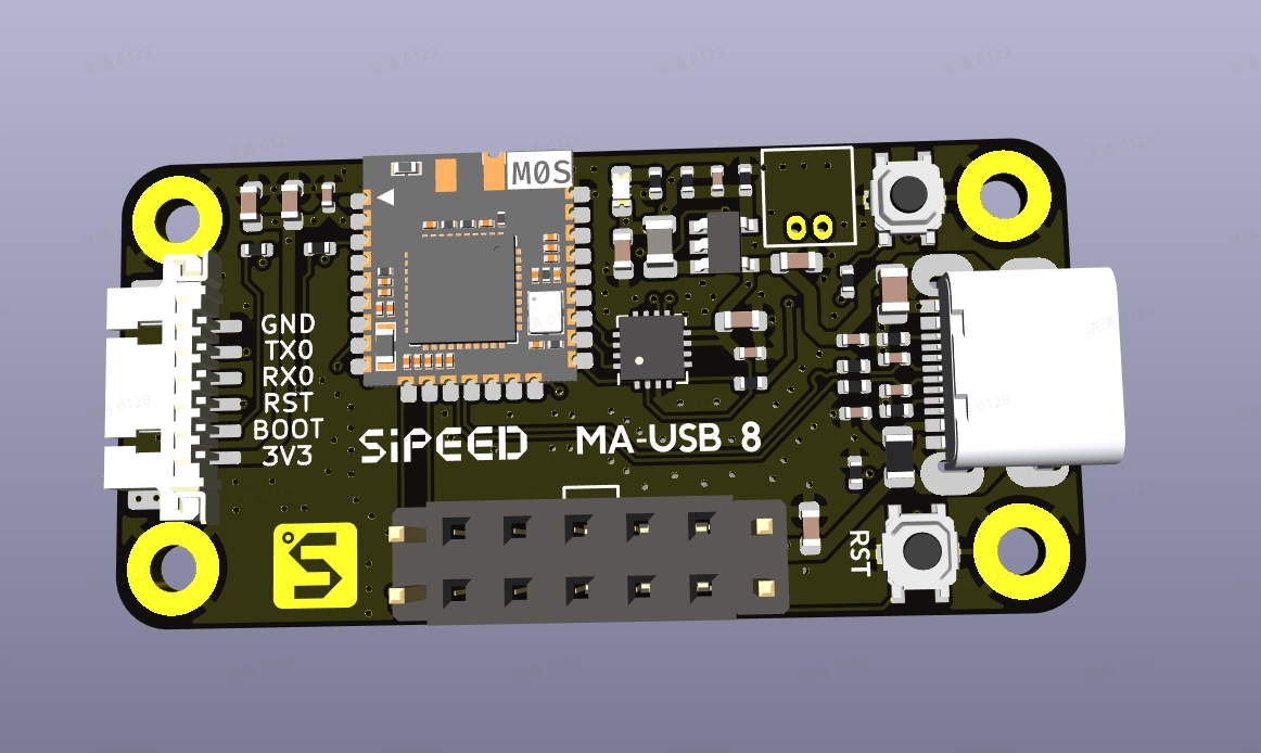
MA-USB8 is a USB audio + serial interface drive board designed for MicArray microphone modules. It forwards the array’s audio (via UAC2.0, 8 channels) and sends soundfield hotmap frames (via CDC ACM or UART) to a host PC or MCU. Common use cases include voice capture, noise suppression, beamforming, and soundfield visualization.
- UAC2.0 (USB Audio Class): 8 channels, PCM S16_LE, 48 kHz
- CDC ACM (USB virtual COM): 16×16 raw hotmap frames
- UART: 16×16 raw / HEX + pseudo-color hotmap frames at 2,000,000 bps (suitable for MCUs)
The UAC channels are defined as follows:
| Channel | Data |
|---|---|
| CH0–CH5 | Raw signed 16-bit PCM captured by PEC |
| CH6 | Time-aligned average of CH0–CH5, used as the beamformed output |
| CH7 | Raw signed 16-bit PCM captured by PEC |
All channels use a 48 kHz sample rate. During UAC streaming, the raw PEC data for CH6 is replaced by the beamformed result.
Beam direction and physical microphone order
View the front of the microphone array with its connector and flat edge at the bottom. MIC0 (CH0) is at the top; MIC1–MIC5 (CH1–CH5) continue clockwise around the outer ring. Serial commands 0,1,..9,A,B start at MIC0 and select the beam direction clockwise in 30° steps:
| Command | Angle | Physical direction |
|---|---|---|
0 |
0° | MIC0 / CH0 |
1 |
30° | Between MIC0 and MIC1 |
2 |
60° | MIC1 / CH1 |
3 |
90° | Between MIC1 and MIC2 |
4 |
120° | MIC2 / CH2 |
5 |
150° | Between MIC2 and MIC3 |
6 |
180° | MIC3 / CH3 |
7 |
210° | Between MIC3 and MIC4 |
8 |
240° | MIC4 / CH4 |
9 |
270° | Between MIC4 and MIC5 |
A |
300° | MIC5 / CH5 |
B |
330° | Between MIC5 and MIC0 |
See the placement drawing in the microphone array module guide for the physical numbering. CH6 is the beamformed output; it does not represent a seventh physical direction.
This document is a user guide for MA-USB8. It covers connection, device verification, audio capture, beamforming, how to read/parse hotmap frames, and common troubleshooting.
Quick start
Hardware and basic setup
- Use a data-capable 5V USB cable.
- Connect MA-USB8 to your host PC or to your MCU board via USB/USB2TTL.
- Choose a mode:
- Preferred: USB (UAC2.0 audio + CDC ACM serial) — on PC you can get multi-channel audio and hotmap frames together.
- Alternate: UART / USB2TTL (2,000,000 bps) — for MCU/embedded environments to get hotmap frames (HEX/pseudocolor) only.
We recommend installing Audacity on your PC for testing/recording.
Before proceeding, check:
- That the USB cable is firmly connected and the board is powered (check LEDs).
- That the device appears in your system (Linux:
/dev/ttyACM0or/dev/ttyUSB0; Windows: look for MA-USB8 audio/CDC device in Device Manager).
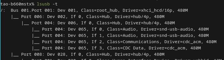
Verify the device (Linux)
- After plugging in, run:
dmesg | tail— you should see/dev/ttyACM0andSipeedUSB MicArray.lsusb— to inspect device IDs.
- Check audio devices with:
arecord -l— you should find an 8-channel UAC device.pactl list short sources— PulseAudio users can check sources.

Verify the device (Windows)
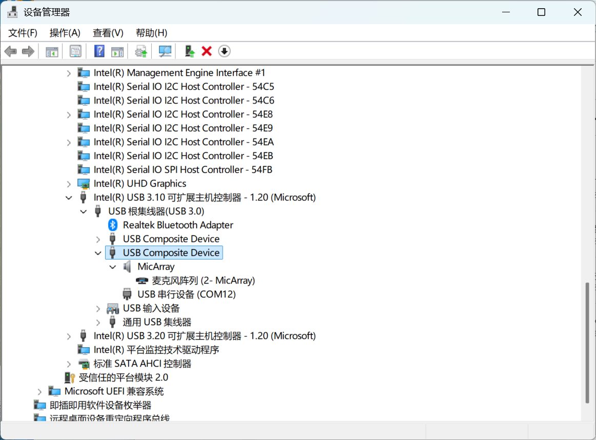
Open Device Manager and confirm the device appears as a multi-channel audio device and a CDC ACM serial port. Use software that supports multi-channel UAC capture (e.g., Audacity configured with WASAPI) to record all 8 channels.
If recording software offers only 1 or 2 channels, see Windows offers only 1 or 2 channels.
Record 8 channels (UAC2.0)
Linux (CLI)
Find the card/device and record 8 channels using arecord:
arecord -l  # find the card / device
arecord -D hw:1,0 -f S16_LE -c 8 -r 48000 -t wav -d 10 test_8ch.wav
Extract and play one channel (e.g., CH6):
sudo apt install sox
sox test_8ch.wav ch6.wav remix 7  # sox uses 1-based channel indexing; `remix 7` extracts CH6 (zero-based→1-based)
aplay ch6.wav
Notes:
- Device indexes and channel mapping may vary between systems and drivers. Use
arecord -l/aplay -lto confirm hw index and channel mapping. - If you cannot access a serial device on Linux, see Cannot access a serial device on Linux.
Audacity (GUI)
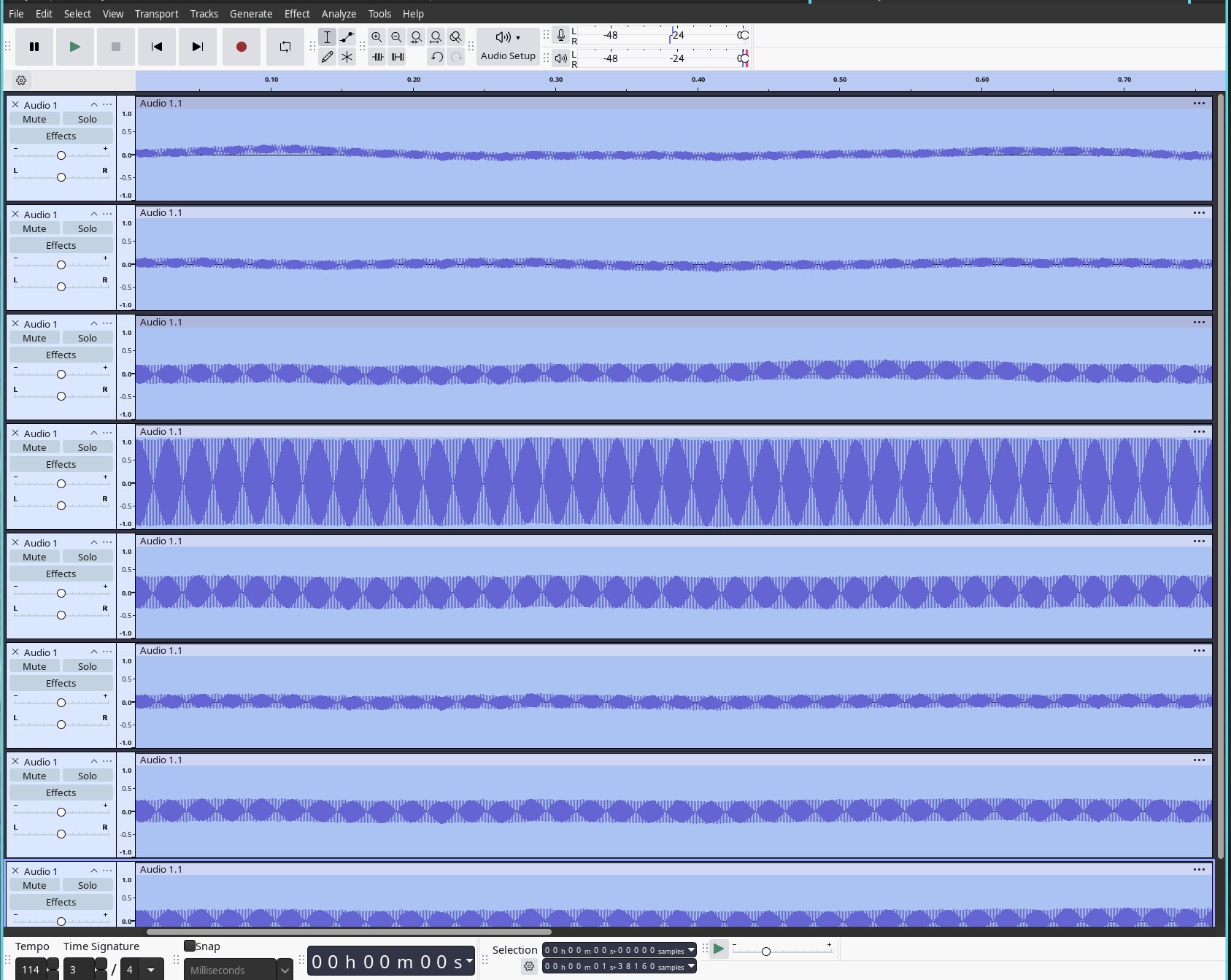
- Open Audacity → Edit → Preferences → Devices, and select MA-USB8 as the recording device.
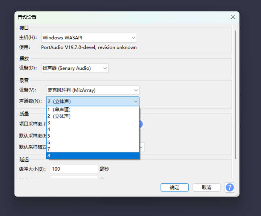
- Choose the number of channels (8) in the recording options.
- Record and inspect the tracks; you can solo or export an individual channel as needed.
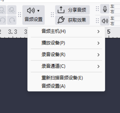
Windows: Select WASAPI. If only 1 or 2 channels remain available, see Windows offers only 1 or 2 channels.
Beamforming demo
MA-USB8 supports 12 beamforming directions: 0..9, A, B (each step = 30°).
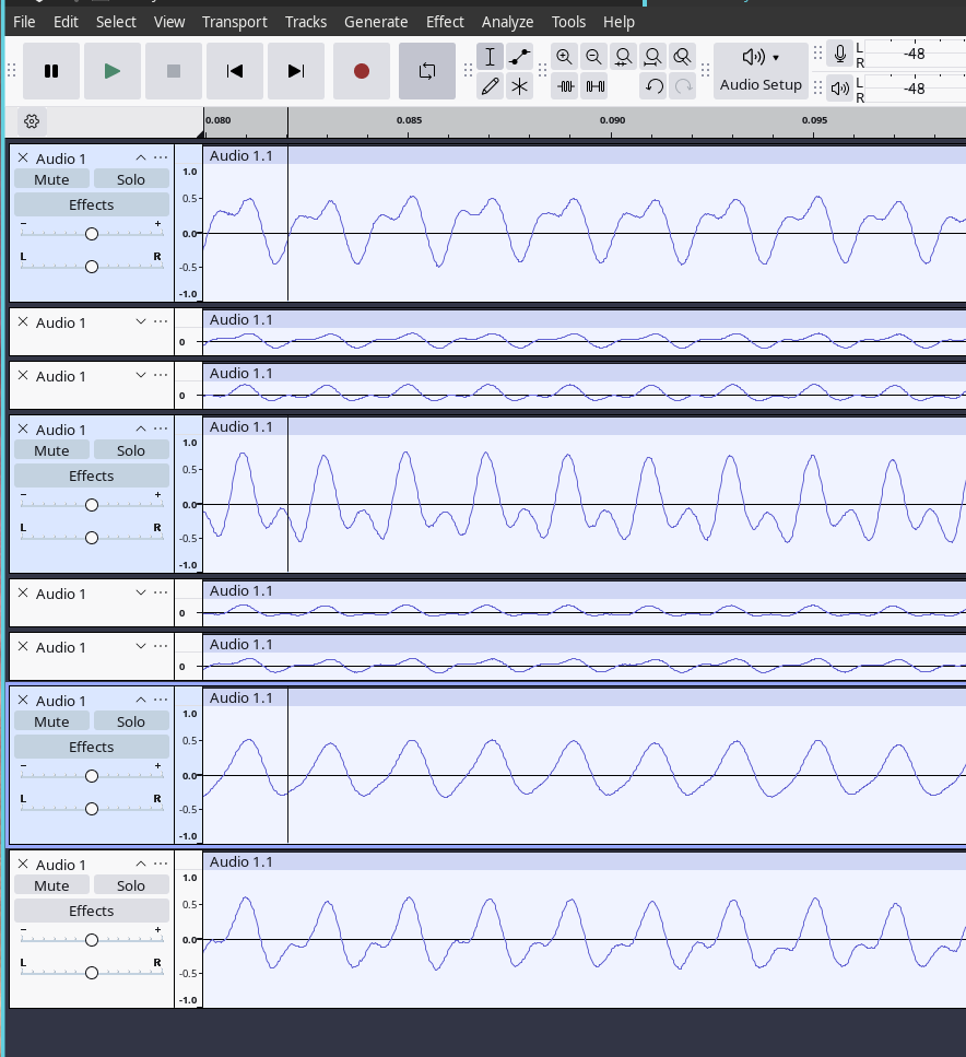
To point the beam to CH0 (0°) and monitor the beamformed output on CH6:
- Open the CDC ACM serial device (e.g.,
/dev/ttyACM0) with a serial terminal:
minicom -D /dev/ttyACM0 -H
- Type a single character (e.g.,
0) to set the beam direction to 0°. The beamformed audio will be output on CH6. - Record or play CH6 and confirm that sound from the selected direction is amplified and other directions are suppressed.
Note: 0..9, A, B map to angles 0°, 30°, …, 330°.
Observe hotmap frames (CDC ACM / UART)
The board outputs sound-field hotmaps through CDC ACM (/dev/ttyACM0) or UART at 2,000,000 bps. Their default output modes differ:
- CDC ACM continuously outputs raw binary data. Each frame contains a 16-byte header and 256 bytes of data; see Hotmap Frame Format.
- UART outputs raw binary data by default. Send uppercase
Fto enable the 16×16 text hotmap, then uppercaseCto enable pseudo-color. Lowercasefandcdisable the corresponding functions; see the Full command table.
Quick check with minicom / picocom
Use minicom to inspect raw CDC ACM frames:
minicom -D /dev/ttyACM0 -H
Use picocom for UART; the baud rate is fixed at 2,000,000 bps:
picocom -b 2000000 /dev/ttyUSB0
After opening picocom, send uppercase F to switch from the raw binary stream to the 16×16 text hotmap. Send uppercase C to add pseudo-color.
If the serial port has no data or its output is garbled, see CDC ACM does not output hotmaps and UART output is garbled.
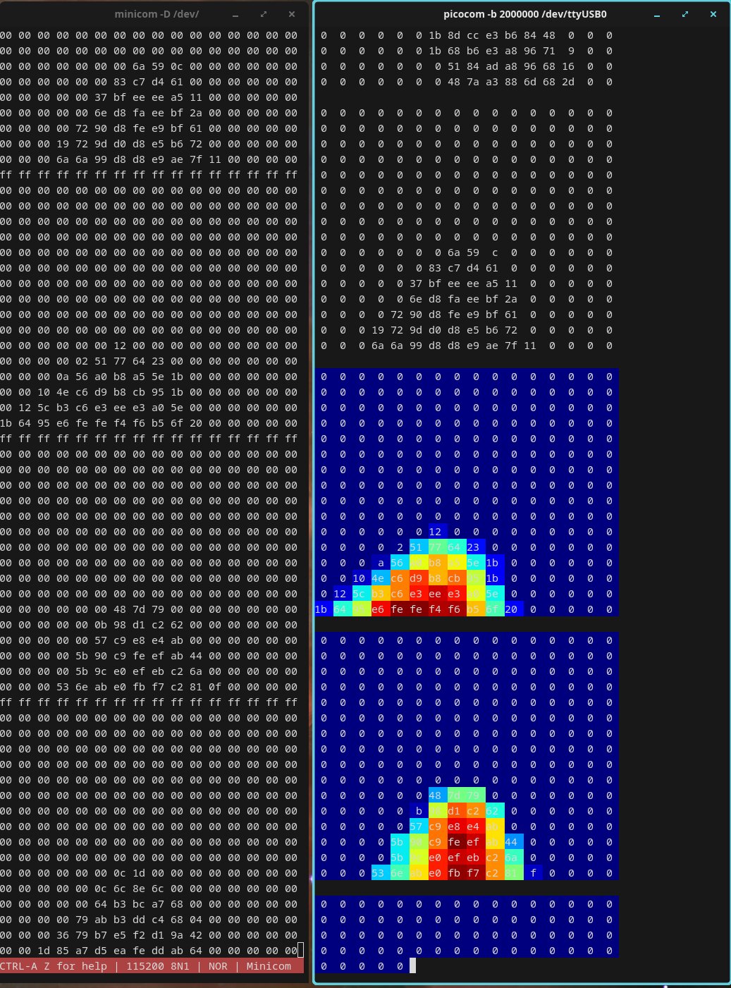
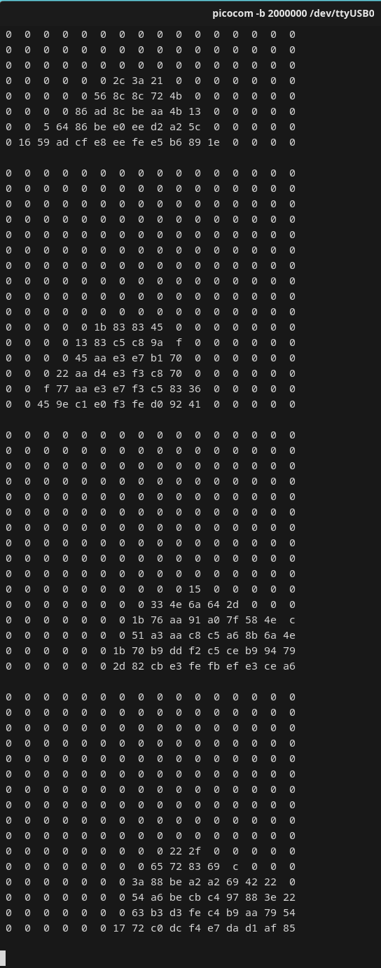
F to enable it.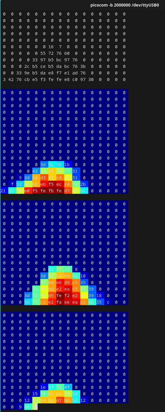
C after enabling 16×16 printing.Quick serial commands (user cheat sheet)
- Set beamforming direction: send
0..9,A, orBto the serial port; CH6 will be the beamformed output. - LED on/off:
e(off) /E(on). - UART 16×16 ASCII hotmap:
fdisables it andFenables it.
Other developer-level commands are shown in the Developer Reference section.
Troubleshooting
Windows offers only 1 or 2 channels
Select WASAPI, then open Settings → System → Sound → Input → MicArray and set Audio Enhancements to Off. Reopen the recording application. Windows effects such as Voice Clarity may limit the recording formats available to applications to 1 or 2 channels.
Cannot access a serial device on Linux
If /dev/ttyACM0 or /dev/ttyUSB0 is not accessible, add the current user to the plugdev group and sign in again:
sudo usermod -a -G plugdev $USER
Alternatively, create a udev rule (replace the vendor/product ID as needed):
# /etc/udev/rules.d/99-ma-usb8.rules
SUBSYSTEM=="tty", ATTRS{idVendor}=="359F", MODE="0666", GROUP="plugdev"
CDC ACM does not output hotmaps
Confirm that the board is operating in CDC ACM/UAC mode rather than UAC-only mode. Close other applications using the serial port, then reopen it.
UART output is garbled
Confirm a baud rate of 2000000 bps, and use picocom -b 2000000 or minicom -b 2000000. On Windows, install the correct USB-to-serial driver for the adapter, such as CH340/CH341/CH552.
Firmware
This page provides only the firmware for the standard MA-USB8 D80 board:
MA-USB8 D80 (2026-08-13)
- Array: standard D80 board, 40 mm radius and 80 mm diameter
- File: MA-USB8-D80-260813.bin
- Size: 4079640 bytes
- SHA-256:
bf9f644783023a0bbe0fffb17c1da325c8756fb5b36c0fb9211f81e5e2f3ce01
This file is an integrated flash image. Follow the procedure below to install it directly.
Do not use this firmware with a D107 array.
Upgrade procedure:
- Download the firmware and verify its size or SHA-256 checksum.
- Follow the combo8 firmware update guide to connect the device, enter flashing mode, and write the firmware.
- Disconnect and reconnect the device after flashing completes.
- On Linux, use
lsusb -vandarecord -l; on Windows, use Sound settings to confirm that MicArray provides 8-channel, PCM 16-bit, 48 kHz audio. - If Windows recording software still offers only 1 or 2 channels, see Windows offers only 1 or 2 channels.
Record the current firmware version and USB descriptors before upgrading so that you can compare the device state if flashing fails. Do not disconnect USB or close the flashing tool during the upgrade.
Developer Reference (protocol and full command list)
Hotmap Frame Format
| frame | bytes | value |
|---|---|---|
| head | 16 | 16 × 0xFF |
| data | 16×16 | 256 bytes (one byte per cell, 0..255), row-major order (HxW) |
Total packet length = 16 + 256 = 272 bytes. The header is used for frame alignment and detection; payload is the 256-byte matrix of intensity values.
Full command table
| Command | Input (Lower/Uppercase: Off/On) | Default | Remarks | Input Source |
|---|---|---|---|---|
| Set UAC CH6 beam direction | 0..9, A, B | 0 | Selects clockwise in 30° steps from MIC0 / CH0; see Beam direction and physical microphone order. CH6 carries the beamformed output. | Any (serial/CDC) |
| Adjust source localization activation threshold | t/T | 650 | t: decrease by 50; T: increase by 50; adjustable range: 0–2000 | Any (serial/CDC) |
| UART sound-map pseudocolor toggle | c/C | c | Requires ASCII 16×16 printing enabled | UART only |
| UART internal debug info toggle | d/D | d | Enables/disables debug output | UART only |
| LED indicator toggle | e/E | E | E = on, e = off | Any |
| UART 16×16 ASCII print toggle | f/F | f | Toggle printing 16×16 sound-field map as ASCII | UART only |
| Restore defaults | R | - | Restore board default settings | Any |
udev & Permission (Linux)
Create a udev rule if needed (replace vendor/product with your device’s lsusb IDs):
# /etc/udev/rules.d/99-ma-usb8.rules
SUBSYSTEM=="tty", ATTRS{idVendor}=="XXXX", ATTRS{idProduct}=="YYYY", MODE="0666", GROUP="plugdev"
# Example (Sipeed vendor id)
SUBSYSTEM=="tty", ATTRS{idVendor}=="359F", MODE="0666", GROUP="plugdev"
Serial/USB Notes
- CDC ACM (
/dev/ttyACM0) is bound to the Linuxcdc_acmdriver. If hotmap frames don’t appear, ensure the device is not held by another program. - UART (
/dev/ttyUSB0) typically uses USB-to-serial adapters (CH34x/CH340/CH552); install proper drivers on Windows if necessary.